CALIMET CM9-M1 Sliding Gate Operator Owner’s Manual

CALIMET CO, INC.
9949 HAYWARD WAY, SOUTH EL MONTE, CA 91733
TEL: 626.452.9009 | TECH: 626.996.0128 | WWW.CALIMETCO.COM
OVERVIEW
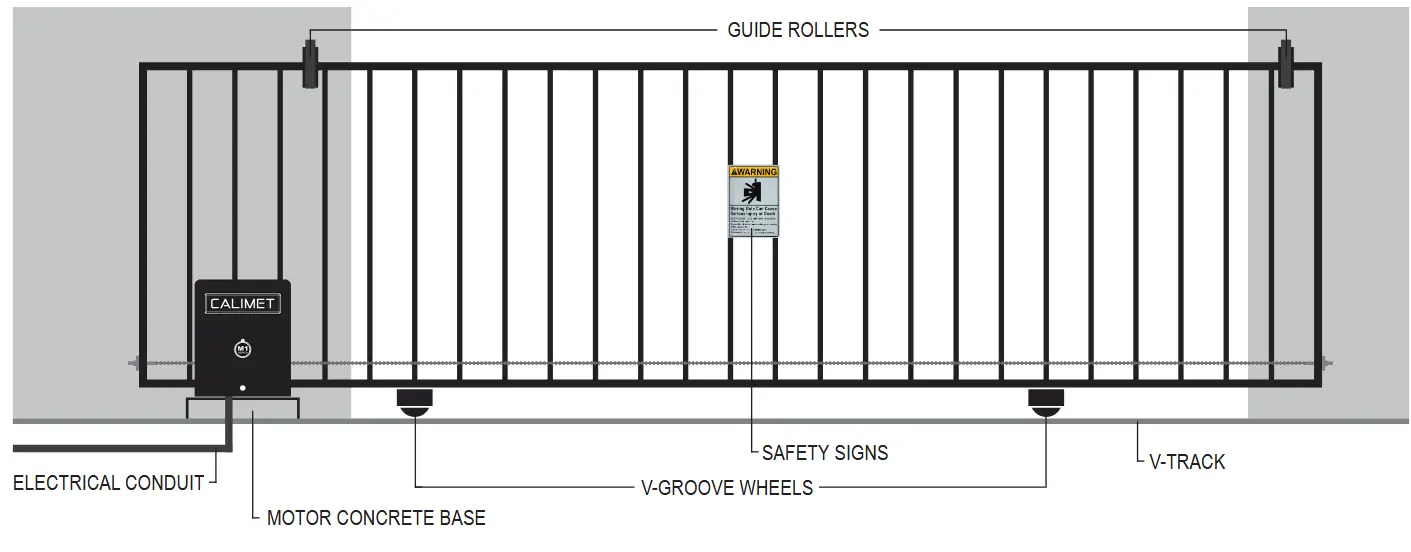
GATE OPERATOR OVERVIEW


SAFETY (MUST READ)
Carefully read follow, and accept all safety precautions and warnings before attempting to install and use the sliding gate operator, incorrect installation can lead to severe injury or death.
– The gate operator must be installed by a certified (licensed) gate technician; otherwise serious personal injury or property damage may occur.
– Installing a gate operator may require installation of standard 110V – 120V AC electrical wiring. This work should only be performed by an experienced electrician. Miswiring could cause personal injury or death.
– Never let children operate the gate or play around the gate. Keep the remote control away from children.
– Always keep people and objects away from the gate. Cars, people, and objects should never enter when the gate is closing.
– Verify that this operator is proper for the type, weight, and size of the gate.
– Make sure the gate has been properly installed and slide freely in both directions with no resistance. Repair or replace all worn or damaged gate hardware prior to installation.
– Test gate operator monthly. The gate must reverse when comes in contact with a solid object, or stop when an object activates the non-contact sensors. After adjusting the force or travel limit, the gate operator must be reset. Failure to maintain the gate operator properly can increase the risk of injury or death.
– The key emergency release should only be used when the gate is not moving.
– Keep the gate and gate operator properly maintained. Read the maintenance section of this manual and follow the maintenance schedule. Gate operator’s hardware(s) must be repaired or installed by a certified service technician.
– Gate operator can use a huge amount of force to open and close the gate. Therefore, safety features must be taken into consideration when installing and using a gate operator. Specific safety feature include: photoelectric sensors (non-contact), edge sensors (contact), moving gate warning signs, guards for exposed rollers, screen mesh, vertical posts, and more.
– The gate must be installed in a location so that enough clearance is supplied between the gate and adjacent structures when opening and closing to reduce the risk of entrapment.
– Entrapment is defined as when a person, vehicle, or object is caught or held in a position that increases the risk of injury.
– Access controls intended for users must be located at least 6 feet (1.8m) away from any moving part of the gate and where the user is prevented from reaching over, under, around, or through the gate to operate the controls.
– A minimum of two (2) warning signs shall be installed, one on each side of the gate that is easily visible.
– Gate automatic closed timer function isn’t recommended unless edge sensor/loop detectors are installed.
– The gate must have sufficient room when opening and closing. Swinging gates should open inwards and not into public access areas. The gate must be properly installed and move freely in both directions.
– Install the gate operator only when: 1) The operator is appropriate for the construction of the gate and the usage class of the gate, 2) All exposed pinch points are eliminated or guarded.
– For gate operators utilizing Type D protection: 1) The gate operator controls must be placed so that the user has full view of the gate area when the gate is moving, 2) The placard shall be placed adjacent to the controls, 3) An automatic closing device (such as timer, loop sensor, or similar devices) shall not be employed, and 4) No other activation device shall be connected.
– The gate operator is intended for installation only on vehicular gates. Pedestrians must access a separate entrance. The pedestrian entrance shall be designed for pedestrian usage. The gate must be installed in a location so that pedestrians will not come in contact with the vehicular gate during the entire path of travel of the vehicular gate.
– For gate operators utilizing a non-contact sensor, 1) see instructions on the placement of non-contact sensors for each Type of application, 2) Care shall be exercised to reduce the risk of nuisance tripping such as when a vehicle, trips the sensor while the gate is still moving, and 3) One or more non-contact sensors shall be located where the risk of entrapment or obstruction exists, such as the perimeter reachable by a moving gate or barrier.
– For a gate operator utilizing a contact sensor: 1) one or more contact sensors shall be located at the leading edge, trailing edge, and post mounted both inside and outside of a vehicular gate. 2) One or more contact sensors shall be located at the bottom edge of a vehicular vertical lift gate. 3) One or more contact sensors shall be located at the pinch point of a vehicular vertical pivot gate. 4) A hardwired contact sensor shall be located and its wiring arranged so that the communication between the sensor and the gate operator is not subjected to mechanical damage. 5) A wireless contact sensor such as one that transmits radio frequency (RF) signals to the gate operator for entrapment protection functions shall be located where the transmission of the signals are not obstructed of impeded by building structures, natural landscaping or similar obstructions. A wireless contact sensor shall function under the intended end-use conditions.
– Controls intended to be used to reset an operator after two (2) sequential activations of the entrapment protection device(s) must be located in the line-of-sight of the gate. Outdoor or easily accessible controls shall have a security feature to prevent unauthorized use.
PROPERTY TYPES & ENTRAPMENT PROTECTION
Required Entrapment Protection
A – Inherent (built-in) Entrapment Protection System
B1 – Non-contact sensor such as a photosensor or equivalent
B2 – Contact sensor such as edge sensor or equivalent
C – Inherent adjustable clutch or pressure relief device
D – Actuation device requiring contrinuous pressure to maintain gate motion
E – Inherent Audio Alarm
Class I – Residential
Intended for use in a home of one (1) to four (4) single family dwelings, garage or parking area associated therewith
Swing Gate Requirements: Primary Device: A, C
Secondary Device (one required): A, B1, B2, C, D
Class II – Commercial
Intended for use in a commercial location or building such as a multi-family housing unit (five or more single family units, hotel, garages, retail store or other building servicing the general public.
Swing Gate Requirements: Primary Device: A, C
Secondary Device (one required): A, B1, B2, C, D
Class III – Industrial
Intended for use in an industrial location or building such as a factory, loading dock area, or other locations not intended to service the general public.
Swing Gate Requirements: Primary Device: A, B1, B2, C
Secondary Device (one required): A, B1, B2, D, E
Class IV – Restricted Access
Intended for use in a guarded industrial location or building such as a military base, hazardous chem sites, or other restricted access locations, in which unauthorized access is prevented via supervision by staffs.
Swing Gate Requirements: Primary Device: A, B1, B2, C, D
Secondary Device (one required): A, B1, B2, C, D, E
NOTE: A minimum of 2 independent entrapment protection devices are required for each direction of travel. The same type of device shall not be utilized for both the primary & secondary entrapment protection means Use of a single device to cover both the opening & closing directions is in accordance with the requriement; however, a single device is not required to cover both directions.
INSTALLATION
PRE-INSTALLATION
GATE STRUCTURE
Recommended Gate Structure:
Confirm that the gate operator being installed is appropriate for the gate type, weight and size. The gate should be mounted and moving freely. There should be a little resistance in the movement of the gate. The gate & post must be suitable for being automated. Check that the structure is sufficiently strong & stable, and that its dimensions and weights conform to those listed in the specifications table of this document. Any worn or damaged gate hardware must be repaired or replaced before installing the gate operator.
Vehicular gates are to be constructed and installed in accordance with the ASTM F2200 contruction standards.
The gate travel distance may vary due to temperature and other environmental factors. we do not recommend the installation of the catch post (FIGURE A). This can cause the gate to collide with the post. We do recommend the installation of guide rollers (FIGURE B & C) on each side of the gate. The gate should be at lease 4” space with the closing wall (FIGURE D).

ELECTRICAL REQUIREMENTS
Electrical Requirements:
The M1 is powered by 100V – 120V AC power. If you have not already done so, and you are not using solar, wire a waterproof outlet near the gate following proper safety standards for your area. If you are not licensed and /or experienced with this type of wiring, please hire a professional electrician to perform this as well as connect the M1 power line. Make sure your electrician takes into account the voltage drop involved in running many feet of wire to your installation location. If an insufficient gauge of wire is used, the gate operator may have insufficient power.
The gate operator must be disconnected from the power source before the installation. This also includes all gate operator’s accessories.
Electrician Check-List:
- Prepare An Unused 15AMP Breaker Dedicated For Gate Operator Power Source.
- Install Electrical Conduit From Electrical Panel To Gate Operator’s Waterproof Outlet.
- Use UL Approved Electrical Wires With Minimum Capacity of 15 AMP.
- Select A Correct Wire Gauge Base On The Wire Distance:
1 – 200 FT (14 AWG), 201 – 400 FT (12 AWG), 401 – 650 FT (10 AWG), 651 – 1000 FT (8 AWG). - Wire Connection Order: 1st. Ground Wire, 2nd. Negative Wire, 3rd. Positive Wire.
- If Ground Wire Is Not Available, Gate Operator’s Ground Wire Must Be Grounded.
- All Power Outlets And Wire Connections Must Be Cover, Water Resistance, And Off The Ground.
![]()
RISK OF ELECTRIC SHOCK. COULD RESULT IN SERIOUS INJURY OR DEATH.
Only qualified personnel should service this job-site. Disconnect all remote electrical power supplies before servicing. Remove all power and lockout system before plugging and unplugging.
POSITION OPTIONS
Front Position:
This is the standard position. We recommend installing the gate operator near the front.
The gate operator should be installed near the front roller of the gate (FIGURE A).

Rear Position:
The gate operator should be installed near the back of the gate while it open.
Note: An additional idler pulley or gear disc is required in this position (FIGURE B).

![]()
INSTALL THE GATE OPERTOR INSIDE THE PROPERTY
Install the gate operator on the inside of the property and behind the gate. DO NOT install the operator on the outside of the gate where the public has access to it.
PREPARE CONCRETE PAD
It is recommended to install a concrete pad in order to maintain proper stability
- Lay out a concrete pad. Requires a minimum of 18 inches (length) x 18 inches (width) x 24 inches (4 inches height above ground and 20 inches depth below ground).
- Install the electrical conduit: One conduit is required for a single gate. For double gate, add another conduit. If underground loops detectors are installed, add another conduit.
- Pour the concrete pad and make sure the pad is level with the gate. Follow the state building code.
- Used 4 wedge anchors at least 1/2 inches to secure the gate operator to the concrete pad.

![]()
* CONCRETE PAD’S UNDERGROUND DEPTH MAY VARY DUE TO LOCAL BUILDING CODE.
* REINFORCED CONCRETE RECOMMENDED.
* CONDUITS SHOULD BE 6-12” APART FROM ONE ANOTHER TO AVOID INTERFERENCE.
CALL 811 for digging information or contact local underground utility locating companies before digging more than 12 inches deep to avoid damaging underground power, gas, water, or other utility lines.
DUAL GATE INSTALLATION AND WIRING (OPTIONAL)
This setup is for dual sliding gate. A single button press of the remote control can open both gates. This requires two (2) gate operators. The main gate operator is the “MASTER” unit, and the secondary is the “SLAVE” unit.
All accessories including remote controls, photocell sensor, loop detectors, etc. must be installed/programed on the “MASTER” gate operator only. Only one photocell sensor is required, and duo photocell sensor is optional.

Master And Slave Operators Wiring Intruction:
- On the “SLAVE” gate operator, located the main circuit board, and set dip switch number 5 to “ON”.
- Press the reset button on the “SLAVE” gate operator circuit board.
- Locate the DATA + and DATA – green terminal block wire connector on the bottom left of the circuit board. Use a small flathead screwdriver to release the 2 screw on the top to unlock the connector.
- Prepare the electrical wire (18 – 22 gauge, 2 conductor, stranded, copper electrical wire) and connect the master’s “DATA +” to slave’s “DATA +” and master’s “DATA -” to slave’s “DATA -” (once both wires are connected successfully, the “M/S LINK” LED light should blinking green on both MASTER and SLAVE).
- Place the cable underground in an eletrical conduit. This conduit must be separate from the main 110 – 120V AC electricity conduit.
CHAIN’S BRACKETS AND CHAIN INSTALLATIONS
Connect The Chain:
- Open the chain package (CM9-794E) and locate the two 10 FT chain, use the provided 1st Chain Link (pre-installed on one end of the chain) to connect the chain with the 1st chain bolt (FIGURE A).
- Use the 2nd Chain Link to connect both 10 FT chain (FIGURE B).
- Position the gate operator on the concrete pad with the suggested measurements on page 08 and loop the chain through the gear wheels on the back of the gate operator (FIGURE C).

Level And Weld The Chain Brackets:
- Gate at closed position, level the chain’s bracket with the bottom of the idler gear disc (FIGURE D).
- Weld the chain’s bracket to the gate and make sure the chain is level (FIGURE E).
- Confirm the suggested measurements is correct, mark the 6 holds on the operator (3 on each side) and drill 2 inches deep. Use the 1/2” wedge anchor to secure the operator to the concrete pad (FIGURE F).
- Measure the chain to the other end of the gate and weld the chain’s bracket. Bracket must be leveled with the idler gear disc (FIGURE G).
- The chain should have no more than 1 inch (2.5 cm) of sag for every 10 Feet (3 m) of chain length. Chain should not be too tight or too loose, if the chain is too long, adjust the chain bolt position on the bracket or remove links form the chain with the chain cutter tool (CM9-408) until desired length.

Correct Chain Position:

MAIN POWER CONNECTION
- Use UL approved electrical wires, stranded copper, connected to 110-120V AC electricity. Electrical wires MUST have a minimum capacity for 15 AMP current. See (FIGURE B) below for the correct electrical wire gauge size. Wires must be placed in a PVC or other underground conduit.
- Turn off the AC power from the main power circuit breaker.
- Connect the green wire (GROUND) to the ground wire using a wire nut (FIGURE A). If ground wire is not available, connect the green wire to the earth ground rod and the earth ground rod can be grounded to the chassis.
- Connect the white wire to the white wire (NAUTRAL) using a wire nut (FIGURE A).
- Connect the black wire to the black wire (HOT LINE) using a wire nut (FIGURE A).

- All operators MUST be properly grounded in order to prevent an electrical charge. Must use a dedicated circuit for power supply.
- Turn ON AC power from the main power source and turn the power switch on the gate operator to the ON position. For DC Package (backup battery) and S Package (solar power and batteries) model gate operators, turn the battery switch to the ON position (FIGURE C).

![]()
RISK OF ELECTRIC SHOCK. COULD RESULT IN SERIOUS INJURY OR DEATH.
Only qualified personnel should service this job-site. Disconnect all remote electrical power supplies before servicing. Remove all power and lockout system before plugging and unplugging.
BACK-UP BATTERY AND SOLAR POWER (OPTIONAL)
Back-up Battery Installation And Wiring Diagram:
M1-DC Package: “Battery Protection Board” and “Back-up Battery” are preinstalled, power connection is required (PAGE 11). Battery ON/OFF switch must be turn ON (PAGE 11 – FIGURE C).

Solar Power Installation And Wiring Diagram:
M1-S Package: “Battery Protection Board” is preinstalled, and the battery extension cable male connector is located outside of the power box. You will need to connect the back-up battery and 2 included solar panels to the circuit board following the below wiring diagram. DO NOT CONNECT THE MAIN POWER TO THE 110V POWER OUTLET IF SOLAR PANEL IS INSTALLED AND CONNECTED.

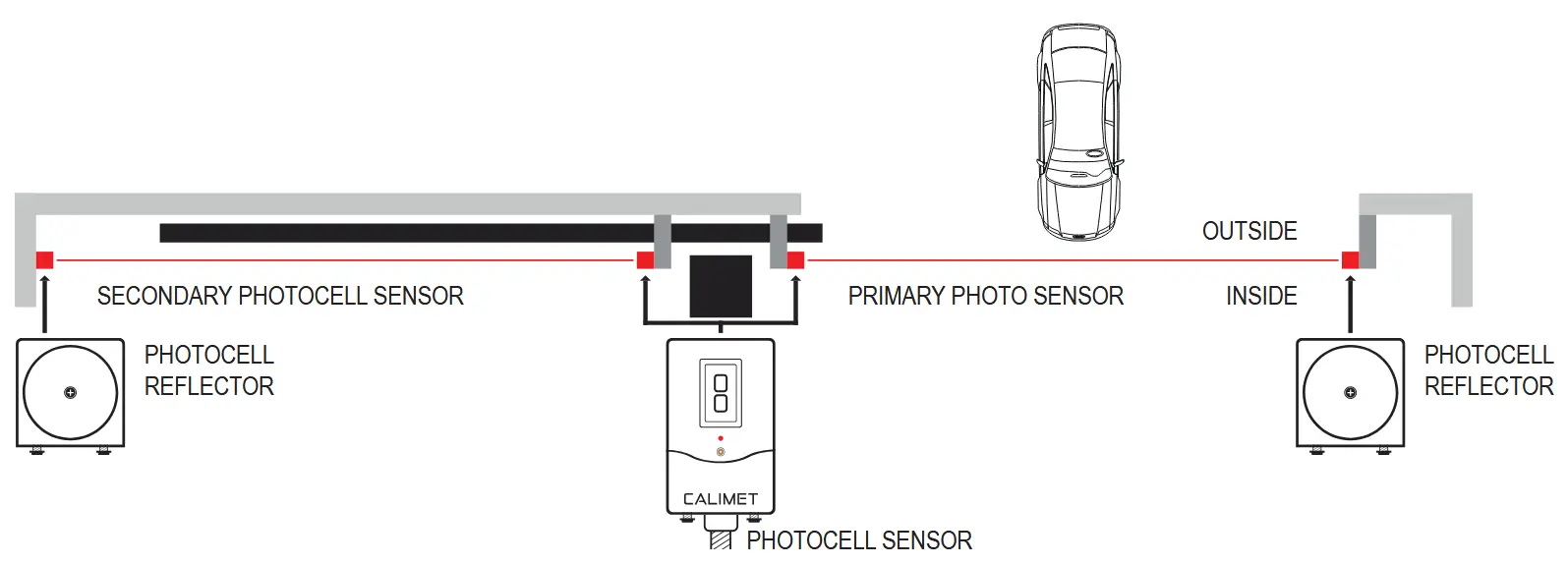
PHOTOCELL SENSOR INSTALLATION
The photocell sensor is a safety device that prevents the gate from hitting a vehicle or pedestrain when the gate is closing. The photocell sensor emits an invisible retroreflective infrared beam that detects when objects passes through.

- Plug the photo-sensor cable to the back of the circuit board box. Refer to “WIRING DIAGRAM” if needed.
- Press the reset button on the circuit board to activate the power for the alignment laser.
- Use the included mounting brackets to mount the photocell sensor. Keep minimum 21” off from ground.
- Press the orange button on the photocell sensor to turn on the alignment laser.
- Mount the reflector to the opposite side and make sure it leveled with the photocell sensor. Laser beam must be inside of the laser effective zone (in side the red area (EXCEPT THE LETTER).
- Press the orange button on the photo-sensor to turn off the alignment laser.
Primary Photocell Sensor Wiring Diagram:

Photocell Sensor’s LED Indicators:
![]() ON – Relay is power, IR Laser beam is inside reflector’s effective zone (aligned). Signal is Stable.
ON – Relay is power, IR Laser beam is inside reflector’s effective zone (aligned). Signal is Stable.
![]() OFF – Relay is NOT power, or IR Laser beam is out of range or outside of the refector’s effective zone.
OFF – Relay is NOT power, or IR Laser beam is out of range or outside of the refector’s effective zone.
Notes:
- The photoccell sensor cannot be used for a detection area less than 6 inches.
- The default sensor maximum range is 30ft. If you need longer range upgrade to 50ft (CM9-487).
- If you need a longer photocell sensor wire, extend it by joining (splicing) with another 20-22 AWG wire.
SECONDARY PHOTOCELL SENSOR (OPTIONAL)
A second photocell sensor can be installed inside the gate to monitor the OPEN cycle.
This secondary photocell sensor goes inside your property, past the gate’s fully open position. If the photocell sensor’s cable isn’t long enough you will need to extend (splice) the wires by joining them with another 20 – 22 AWG wire for the secondary photocell sensor to be able to reach the gate operator input.
Use the same green terminal block input as your primary photocell sensor. Each input can have more than 1 wire inserted. Different model photocell sensors contain 3 or 4 wires.
Secondary Photocell Sensor Wiring Diagram:

![]()
VISIBLE AND INVISIBLE LASER IN USE.
DO NOT stare into the laser beam, serious eye damage may occur.
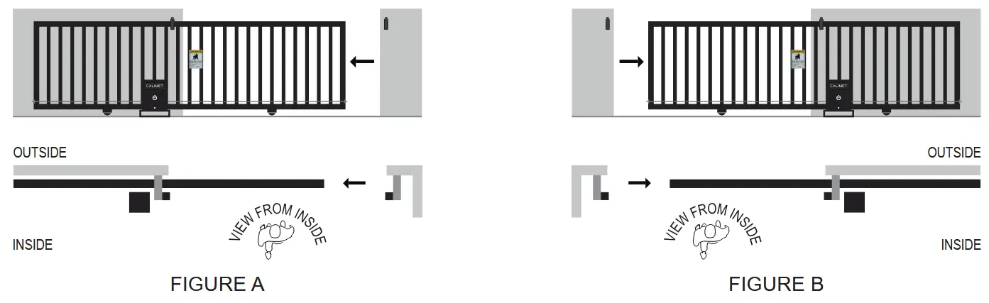
GATE OPENING DIRECTION SETTINGS
Determine which direction your gate opens when VIEWED FROM THE INSIDE:
- GATE OPEN TO THE LEFT SIDE: Dip Switch Number 6 (FIGURE A) is OFF
- GATE OPEN TO THE RIGHT SIDE: Dip Switch Number 6 (FIGURE B) is ON

OPEN AND CLOSE LIMITS ADJUSTMENTS
The Open And Close Limit Adjustment:
- Click the “OPEN” button on main circuit board to move the gate to the desired open position. Once gate is within 1ft, click the “STOP” button.
- Pull and hold the “LIMIT LOCK PLATE” outwards. Turn the “OPEN LIMIT WHEEL” until it touch the open limit switch arm and activated (see below diagram for open direction). Release the “LIMIT LOCK PLATE” and make sure both limit wheels are locked.
- Click the “CLOSE” button on main circuit board and close the gate to half then click “STOP”. Click the “OPEN” button again to open the gate and check if it in the desired position. Make fine adjustments (step 2 and 3) if needed until achived the desired open position.
- Repeat step 1, 2, and 3 on the desired close position.
- Click the “RESET” button once finished and let the circuit board finish study the new travel limit (gate will move very slow). Once it is successfuly learn the new travel limit, gate will give 2 alarm beep sound.

OPEN AND CLOSE (ERD) FORCE ADJUSTMENTS
The Electronic Reversing Device (ERD) is a feature on the circuit board which detects when the gate comes in contact with an obstruction, causing the gate to reverse. These are the 2 blue knobs on the circuit board. The open and close knobs determine the amount of force required to reverse the gate (FIGURE A). We generally recommend leaving the knob at 50. you may adjust the positions based on your particular gate. If the gate reverses without touching an obstruction, the ERD is set too low. if the gate does not reverse when it hits an obstruction, the ERD is set too high.
NOTICE – Test ERD every 6 months.
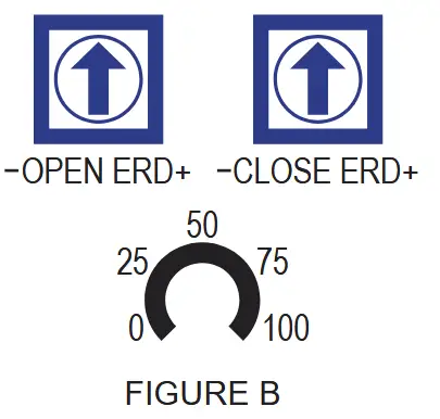
Default 50 – 50 is the default ERD force and is suitable for most gate.
Turn Left (Counter Clockwise) – Less force required to stop the gate.
Turn Right (Clockwise) – More force required to stop the gate.
Obstruction Test:
- Place a light object (ex. chair or trast can) between the open gate and the post.
- Close the gate. the gate should stop and reverse when it touches the object. if the gate does not reverse when it touches the object, press the STOP button on the circuit board. Reduce the ERD force by turning the CLOSE ERD knob counter clockwise.
- Do the same test again for the open direction.
- Test the gate operator after any adjustments are made.
![]()
- Never increase force beyond the minimum amount required to move the gate. TOO MUCH force could result in serious injure or kill.
- Never use force adjustments to compensate for a improperly installed, improperly maintained, or a damaged gate. The gate must normally move freely with no obstructions.
- the ERD must be tested after making any changes. the gate must reserve when it come in contact with an object.
DIP SWITCH FEATURES
There are 8 dip switches located at the bottom of the circuit board (FIGURE A). Each switch controls a different feature of the gate operator.

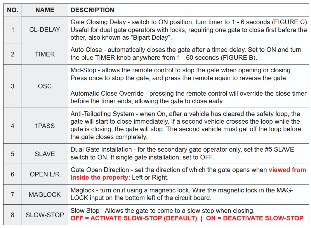
BLUE KNOB “SPEED” (SLOW-STOP SPEED ADJUSTMENT) – Turn left to increases the slow-stop speed and turn right to decreases (FIGURE D).
EMERGENCY RELEASE LOCK
The emergency release lock allow you to open and close the gate manually, in cases during a power outage and there is no other electricity available. Follow the below guide to unlock your gate emergency release:
- Turn the “M1 SERIES” Circle to access to the “EMERGENCY RELEASE” lock and “RESET” button.
- Use the provide key to unlock the “EMERGENCY RELEASE” lock.
- Push the gate open using your hands
- When finished, use the key to lock the “EMERGENCY RELEASE” lock.
- Store the key in the safe area with label for easy access

WARNING SIGNS INSTALLATION
Warning signs are to alert people that a possible hazard exists with moving gates, so that appropriate action can be taken to avoid injury.
Install the 2 supplied warning signs in locations where the signs are visible by people on both sides of the gate. they may be installed directly on the gate. or a nearby wall or post.
Use self-drilling metal screws (NOT INCLUDED) to install the warning signs.

MAIN CONTROL CIRCUIT BOARD LAYOUT

- Photocell Sensor Port
- Keypad/Receiver Port
- Remote Dip Switch And ON/OFF Switch
- Remote Dip Switch And ON/OFF Switch
- 24V Solar Port
- 24V Battery Port
- Fuse Port
- Alarm Speaker
- Motor Sync Cable Port
- Slow-Stop Speed Control Knob
- Timer Time Control Knob (In Second)
- Delay Time Control Knob (In Second)
- OPEN/CLOSE ERD Force Control Knob
- Antenna Port
- Control Buttons (Reset / Close / Stop / Open)
- Electric / Solenoid Lock Port
- Magnetic Lock Port
- Dual Gate Master/Slave Port
- Dip Switches Features
- LED Status Lights
- Common Global Port
- Accessories Port
- Open / Close Limit + 2 Extra Common Port
- Motor Power Port
- AC Power Port
- Circuit Board Version
CIRCUIT BOARD LIGHT STATUS AND ALARMS

The alarm will sound in these following situations:
- Photocell Sensor Obstruction / Misalignment – an object has crossed the photocell infrared beam when the gate was closing. If nothing interrupted the beam, the photocell sensor may be misaligned. Align photocell sensor with the reflector on the other side to fix the problem.
- Impact Detection – The gate operator has a built-in impact sensor called the ERD. If the gate collided w/ an object, the alarm will sound. If there was no collision, the ERD force may be set too low. increase the force to fix the issue. Another possible issue is that the chain may be bent or not correctly aligned to the sprocket.
- Low Battery – Battery is low. Recharge using solar panel or AC electricity. DCFP models only.
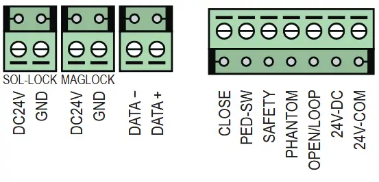
ACCESSORIES WIRING
ACCESSORIES WIRING
Most accessories can be wired into the “Accessories Port” by following the wiring intruction from accessories user manual.
Normal Open (N/O) = OPEN/LOOP
Normal Close (N/O) = CLOSE
Power (Positive Line) = 24V-DC
Common (Negative Line) = 24V-COM
Accessories Input Terminal Ports Commonly Used For:
- Exit Wand
- Loop Detectors
- Fire Access Box
- Digital Timer
- Magnetic Lock
- Solenoid Lock
Accessories Input Terminal Ports Commonly Used For:

- Open and Close Photocell Sensor
- Safety Edge Sensor (Wire)
Accessories Input Terminal Ports Commonly Used For:

- Radio Reciever
- Wire Keypad
ACCESSORIES INSTALLATION
REMOTE CONTROLS
By default, the included remote controls are already connected to the gate operator. You do not need to do any of the following steps unless you are adding more remote controls to your system. This gate operator can add up to 50 remote controls. If you need more than 50 controls, you need to add an extra receiver (CM9-493), which can add up to 100 additional remote controls. Calimet remote controls use 418 MHz frequency with a 300’ max distance. there are two ways to connect: Learn and Dip Switch.
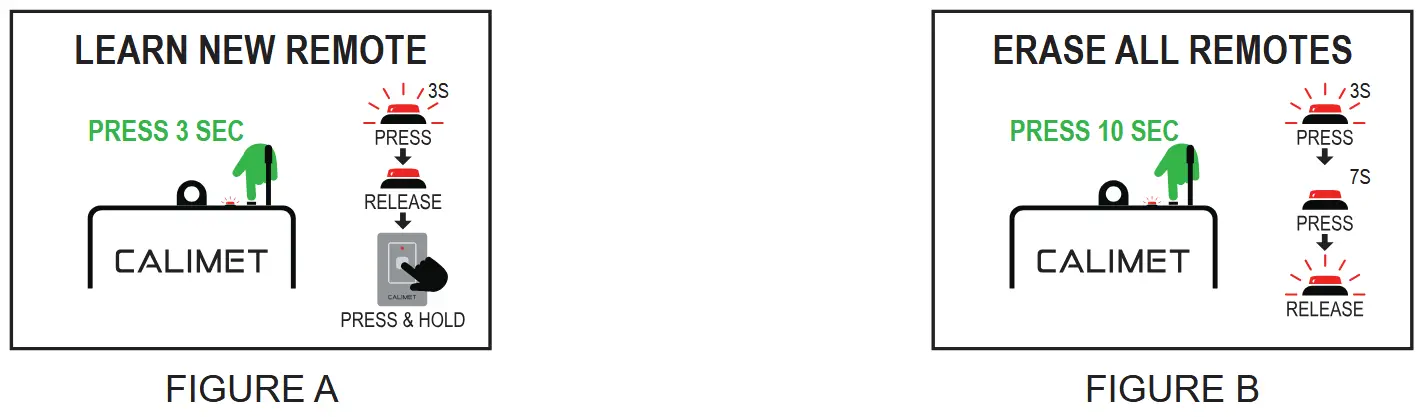
Program By Learn (CM9-864, CM9-510, CM9-510B):
Learn New Remote (FIGURE A):
- Press and hold the “LEARN” button until the flashing light turn solid then release immediately.
- Press + hold the button on the remote control until light flashing again. Remote is now connected.
Remove All Existing Remote Control (FIGURE B):
Press and hold the “LEARN” button for 8 to 10 seconds (flashing – solid – flashing) then release.

Program By Dip Switch (CM9-509):
- Located the “DIP SWITCH OFF/ON” switch on main circuit board. Turn it “ON” (FIGURE C – STEP 1)
- On the left of the ON/OFF Switch, you will find a 1-8 dip switch. Set a random switch combination to created your own code (FIGURE C – STEP 2)
- Unscrew the back of the remote control to gain access to the control circuit board. Your should see 1-8 dip switches. Set the same 1-8 dip switch combination as you did on the main circuit board.
NOTICE – Do not share your dip switch code and keep it safe. Anyone have access to your code will have access to your gate system.
Program With Homelink Remotes:
Most modern cars come with a feature called Homelink that lets you open your gate by pressing a Homelink‘s button on your car. Calimet gate operators are compatible with Homelink. To set up Homelink please visit: “homelink.com/program/vehicle” and enter your car model to view specific instructions. For order cars, or cars with software that isn’t Homelink, check your car’s manual for setup instructions.
WIRELESS KEYPAD
Wireless keypad is a convenient and secure access control solution designed to manage entry to properties without the need for traditional wired connection. It allows users to control gate access remotely by entering a PIN code, offering a flexible, easy-to-install option for both residential and commercial applications.
Change The PIN Code:
- Default PIN is “0000”, press “0000” and press “*” to test if the password is set as default. If yes move to step 3. If no, follow step 2.
- To reset your PIN to default “0000”, you need to use the provided keys to open the keypad. Press and hold the black button until long beep end, then release (FIGURE A – STEP 1). To test, press “0000” and “*” key, If you hear a long beep (3 sec) it means you reset successful (FIGURE A – STEP 2).
- To change the PIN number, you need to press and hold the “#” key until you hear a long beep, wait until beep sound end (FIGURE B – STEP 1). Press “0000” and “*” then wait for beep sound end (FIGURE B – STEP 2). Press your new PIN from 4 digits to 8 digits (for example “1234” or “12345678”) and press “*” and wait for beep sound end. Repeat the new PIN 1 more time (FIGURE B – STEP 3). Now your new PIN number is updated.
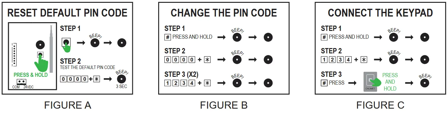
Connect The Keypad To The Gate Operator:
- Press and hold the “#” key until you hear a long beep, wait until beep sound end (FIGURE C – STEP 1).
- Press “1234” (your new PIN number) and “*”, wait until beep sound end (FIGURE C – STEP 2)
- Press “#” and press and hold the remote control (CM9-864), you should here a long beep if successed.
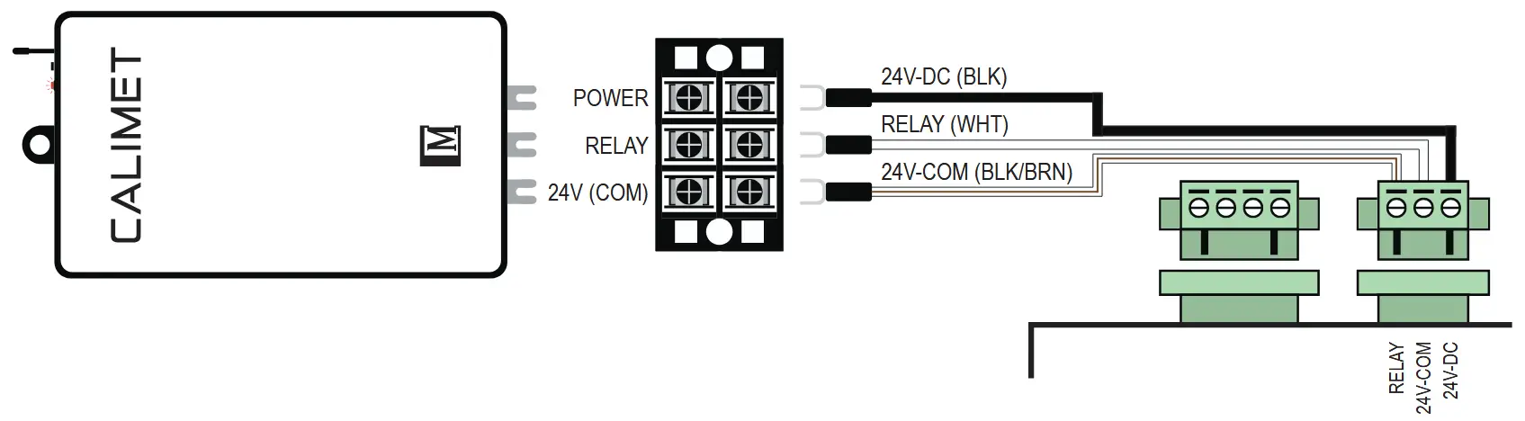
Power Wire Connection Diagram:

ACCESSORIES INSTALLATION: RADIO RECEIVER
Radio receivers provide an additional layer of security by ensuring that only authorized signals can trigger the gate. With a receiver installed, user can add up to 100 additional controls and it operates on 418 MHZ frequency bands, ensuring secure and reliable communication between the transmitter and receiver.
Power Wire Connection Diagram:
Program By Learn (CM9-864, CM9-510, CM9-510B)
Learn New Remote (FIGURE A):
- Press and hold the “LEARN” button until the flashing light turn solid then release immediately.
- Press + hold the button on the remote control until light flashing again. Remote is now connected.
Remove All Existing Remote Control (FIGURE B):
Press and hold the “LEARN” button for 8 to 10 seconds (flashing – solid – flashing) then release.
EXIT BUTTON
Exit button is designed to facilitate smooth and secure vehicle exit from a controlled area. Typically installed at the exit point of parking lots, gated communities, or restricted access facilities, the exit button allows authorized individuals to open the gate without the need for a remote control, keycard, or other access credentials.
Power Wire Connection Diagram:
Note: This is a sample wiring diagram. For detailed installation instructions, please refer to the your Exit Button Installation Manual.

EXIT WAND
Exit Wand is a sensor-based device used to automatically open gates when a vehicle approaches, providing a Seamless and convenient exit experience without the need for manual operation. This technology is particularly useful for automatic gate systems at residential, commercial, and industrial properties where smooth, hands-free exit is needed.
Exit Wand Installation:
- On your concrete drive-way, use a 3/4 concrete bit and drill a 3 inch deep at the desired position.
- Cut a straight line 1 inch deep and 3/16 inch width from the exit wand to the motor.
- Install the exit wand in the hole and make sure it is snug fit to the bottom. You should have 3/4 inch to the ground level.
- Install the exit wand wire (we recommend using electric conduit to extends the cable life).
- Follow the wiring diagram and connect while main power is OFF.

Exit Wand Wire Connection Diagram:

EDGE SENSOR
A edge sensor is a device designed to detect obstacles or pressure along the edge of a gate. It prevents the gate from closing if an obstruction is detected, enhancing safety by preventing injury or damage. The sensor can trigger the gate to stop, ensuring safe operation, especially in high-traffic or residential areas.
Recommend Installation Positions:

Installation Intruction:
- Position the wireless edge sensor on the edge of your gate. Use metal screws to secure it to the gate, and make sure that the air tube is facing down to avoid rain water leak in.
- Mount the aluminum control box bracket facing inside of your gate.
- Slide the edge sensor control box onto the bracket until it secured and make sure the air tube is facing down.
Note: If your edge sensor is too long, you can cut it short by remove the air tube with the edge cover cap, then cut to the desired length. After done, reinstall the cap and air tube (FIGURE A).

LOOP DETECTOR
A loop detector is an safety sensor used to detect the presence of vehicles near a gate, ensuring safe and efficient operation. It typically consists of an inductive loop sensor embedded in the ground, which detects changes in inductance when a vehicle passes over or stops above it. This information is sent to the gate control system, triggering the gate to open and/or stay open. Loop detectors are commonly used in parking lots, driveways, and automated gate systems to automate access and prevent damage to vehicles or the gate itself. There are three type of Loop:
- REVERSE LOOP: Keep the gate open when detect a vehicle, This loop is installed outside the gate.
- PHANTOM LOOP: Keep the gate open when detect a vehicle. This loop is installed inside the gate.
- EXIT LOOP: Open the gate and keep the gate open when detect a vehicle. This loop is installed at least 8 – 12 feet away from the gate.
Loop Detector Installation:

Loop Detector Wire Connection Diagram:
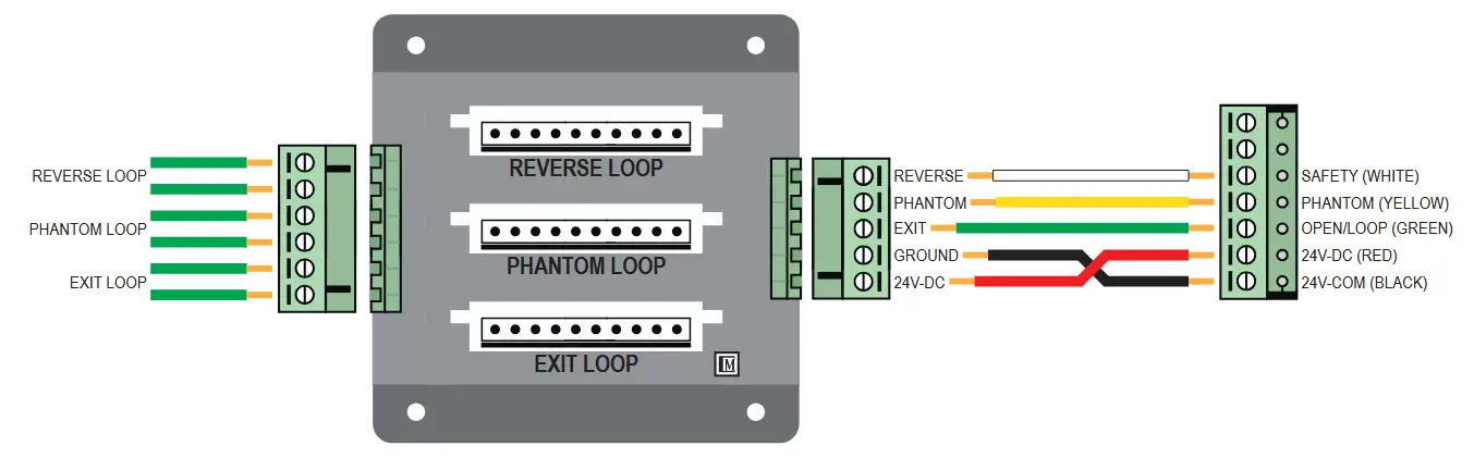
Connect The Loop Detector Control Board:
- Make sure the connection between the loop detector harness and main circuit board is wiring correctly.
- Plug in the RENO MODEL H2 Vehicle Detector in the desire loop slot.
- Connect the loop wire into the correct loop connector.
- Do fine adjustment on RENO MODEL H2 to fullfil the customer’s requirements. For questions regarding on MODEL H2 setting, read RENO manual.
DIGITAL TIMER
A digital timer is a device that controls the timing functions of an automatic gate system. It allows users to set specific times and days for the gate to automatic open and close. These timers help improve the gate’s efficiency, enhance security, and prevent unnecessary wear on the gate mechanism by ensuring it operates within preset time intervals.
Digital Timer Wire Connection Diagram:

Program Digital Timer: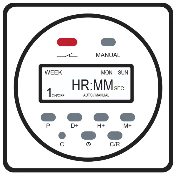
- Use a pin and press “C”, once digital screen is reset.
- Press “D+” to set current day, “H+” hour, and “M+” minute.
- Press “
 ” after finish setting the date and time.
 - Press “P” to select the program setting 1 (total 28 program setting). user should see “1 ON” (opening time). Press “D+” to set the days that needed, “H+” for the hour, and “M+” for the minute.
- Press “P” again to select the program setting “1 OFF” (closing time). Press “D+” to set the days that needed, “H+” for the hour, and “M+” for the minute.
- Follow Setp 4 and 5 until finish programed the timer.
- Press “” after finish.
NOTE: To disable the digital timer, click on “Manual”.
FIRE ACCESS BOX
A fire access box is a safety device designed to provide emergency responders with quick and easy access to gate controls during a fire or other emergencies. Installed near the gate, it typically contains a manual release mechanism or key to override automated gate systems, ensuring that first responders can open the gate without delay. This is especially crucial for gated communities, secure facilities, or areas where the gate might be otherwise difficult to access in an emergency. Fire access boxes help enhance safety and ensure smooth emergency operations.
Fire Access Box Wire Connection Diagram:

Knox Fire Switch Wire Connection Diagram:

MAGNETIC GATE LOCK
A Magnetic Lock is an access control solution that uses electromagnetic forces to securely hold a gate in place. When activated, the magnet creates a strong bond between the gate and the frame, preventing unauthorized access. Magnetic locks are commonly used in automated gate systems for residential, commercial, and industrial properties due to their reliability, ease of use, and ability to integrate with electronic access systems. They offer a high level of security, ensuring gates remain closed until the proper access signal is given.
Maglock Wire Connection Diagram:

ACCESS CAMERA
An Access Camera and SmartGate Mobile App are modern solutions designed to enhance the functionality and security of gate operator systems. The Access Camera provides real-time video monitoring of the gate area, allowing users to visually verify visitors or deliveries before granting access. Integrated with the SmartGate Mobile App (UNLIMITED REMOTE and WORLDWIDE ACCESS), users can remotely control and monitor their gate systems through their smartphones. The app allows for features like opening or closing the gate, viewing live camera feeds, and managing access permissions from anywhere. This combination offers greater convenience, security, and control over gated entrances.
Connect The Camera With The App:
- Plug the camera to the 110V outlet and connect the camera’s antenna.
- Download the SmartGate App on Apple Store (IOS) and our website at www.calimetco.com (Android).
- Create a new account and log in.
- Press on the plug (+) sign on the top right conner to add new camera.
- Click on the blue box “If the device has not been configured….” to open setting window.
- Click WiFi tab on your phone to open WiFi window.
- Use pin to press and hold the button under the red light on the camera box until see a WiFi connection named: “SmartDoorV2-#####”. Click to connect, once successful click on smartgate (top left conner) to go back to the app.
- Rename your gate and input your WiFi username and password. Click on “Binding Device” to connect.
- If everything correct it should show a pop up window with msg: “Binding Success”. Click “OK” and quit the SmartGate App and reopen. Camera should be connected.
Connect The App With The Gate Operator
- Open the SmartGate App and click on the Camera that need to program.
- Open the Motor and have access to the Main Circuit Board.
- Press and hold the study button until the flashing light is solid (PAGE 23 – FIGURE A)
- Press continuely on the PLAY button in the app until the study light on the main circuit board is flashing again. Test if it is connected.
IMPORTANT INFORMATION
MAINTENANCE

MANUFACTURER’S LIMITED WARRANTY
CALIMET CO., INC, warrants the gate operator(s) for a period of three (3) years in commercial installations and for a period of five (5) years in residential installation to be free from defects in mortor, gearbox, circuit board, and workmanship. This warranty is limited to two (2) of any combination of repairs or replacement of parts. This warranty applies from the date of purchase to the original owner. Warrantor will repair or replace (at warrantor’s sole discretion) any part which it finds to require service, excepting that, this limited warranty does not cover the following corrosion and, damage or failures resulting from environmental conditions, vandalism, water, lack of proper maintaince, accident, theft, fire, normal wear and tear, misuse, alteration, tampering, improper repair, installation of non CALIMET approved parts, accessories, or components. This device must be send to the warrantor at the consumer’s expense to:
CALIMET CO., INC.
9949 HAYWARD WAY, SOUTH EL MONTE, CA 91733
The warrantor will return the repaired or replaced unit to the customer at the consumer’s expense. The limited warranty does NOT cover labor fees for reinstalling a repaired or replaced unit or part.
These warranties are in lieu or all other warranties either expressed or implied, and CALIMET CO., INC. shall not be liable for consequential damage. All implied warranties of merchantability and/or fitness for a particular purpose are hearby disclaimed and excluded. This limitation is not valid in jurisdictions which do not allow limitation of incidental or consequential damages or limitation of warranty periods. Please complete the registration card and send it by mail within 30 days of purchasing from CALIMET, DEALER or your INSTALLER. If not registered only a one (1) year warranty on all part will be provided.
The warranty card must be mailed to the address listed on the card with the proof of purchased (Invoice). Alternatively, the warranty can be completed online at https://calimetco.com/warranty and email us your proof of purchased (Invoice) with Email Subject: Full Name, Model #, Serial #.
Important Information
Purchased Date: ______________ Purchased From: __________________________________________
Installed Date: ______________ Installed By: ______________________ Phone No.: _______________
Model No.: ____________________________ Serial Number: __________________________________
Registered Date: ______________ Registered Confirmation No.: ________________________________
![]()
CALIMET CO., INC.
9949 HAYWARD WAY, SOUTH EL MONTE, CA 91733
626.452.9009 | INFO@CALIMETCO.COM | CALIMETCO.COM

https://calimetco.com/
https://calimetms.com/
Documents / Resources
 |
CALIMET CM9-M1 Sliding Gate Operator [pdf] Owner's Manual M1, CM9-M1, CM9-M1 Sliding Gate Operator, Sliding Gate Operator, Gate Operator, Operator |