C AND D CL112A Height Adjustable Table Control
Product Information
Specifications
- Model: CL112A V1.2.2
- Type: Height-Adjustable Table Control
- Compatibility: Works with CL112A Handset V1.2.2
Product Usage Instructions
Initial Setup
- Open the battery cover at the bottom of the controller.
- Insert two AAA batteries into the battery slot, observing the positive and negative electrode signs.
- After installation, the manual controller will display 8.8.8.
- Close the battery cover securely.
Manual Pairing
- The control box enters pairing mode 10 seconds before it is powered on.
- Press the + key simultaneously for pairing.
- Follow the detailed pairing sequence provided in the manual.
User Controlled Operation
Key Icon
- Short press: Desktop raises by 3mm
- Long press: Desktop rises continuously
- Short press: Table drops by 3mm
- Long press: Desktop drops continuously
Reset Operation
If the system reaches the lowest position or encounters a fault, hold down the key for 5 seconds to enter reset mode (RST displayed). The system can be reset by following the instructions provided.
Frequently Asked Questions (FAQ)
- Q: How do I know if the pairing was successful?
- A: A successful pairing is indicated by a specific display on the manual controller and a beep sound from the control box.
- Q: What should I do if the pairing fails?
- A: If the pairing fails, repeat the pairing process as outlined in the manual.
CL108A(Works with CL112A Handset)
V1.2.2
HEIGHT- ADJUSTABLE
TABLE HAND CONTROL MANUAL
Change history
| Version | Change Detail | Date | Responsible/from |
| V1.0 | First Release | 2023-03-21 | Musheng Qi |
| V1.1 | Menu added p08 | 2023-04-21 | Musheng Qi |
| V1.2 | Modify the non-inductive stretch operation logic | 2023-05-07 | Musheng Qi |
Operation Interface
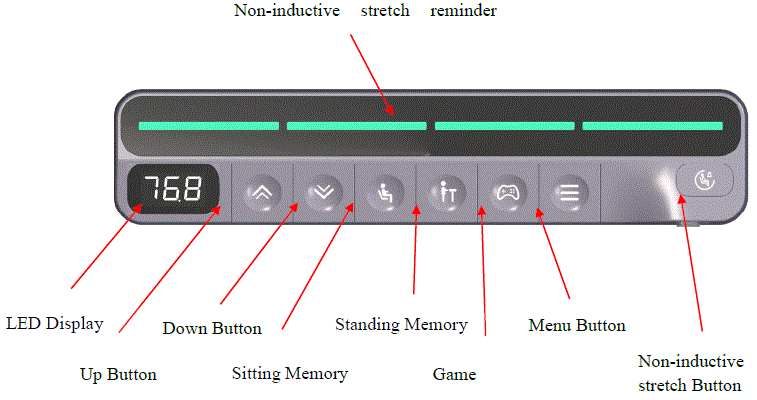
Operating Instructions
| Key |  |
 |
 |
 |
 |
 |
 |
 |
| Default | Up | Down | 750mm | 1100mm | 850mm | Menu | Non-inductive stretch | Child Lock |
Initial Power On
Please open the battery cover at the bottom of the controller, put the two AAA batteries into the battery slot, and pay attention to the positive and negative electrode signs. After it installation, the manual controller will display 8.8.8. Then install the battery cover at the bottom of the controller.
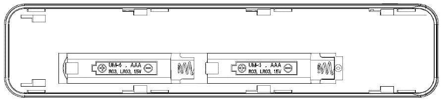
Please open the battery cover at the bottom of the controller, put the two AAA batteries into the battery slot, and pay attention to the positive and negative electrode signs. After it installation, the manual controller will display 8.8.8. Then install the battery cover at the bottom of the controller.
Manual pairing
The control box is in pairing mode 10 seconds before it is powered on. Press the ![]() key at the same time to pairing, the detailed pairing sequence is as follows:
key at the same time to pairing, the detailed pairing sequence is as follows:
- Power off the control box, and then power on again, hear two “beep”, indicating that the control box has been powered on.
- Within 5 seconds of hearing the buzzer sound, press the key
 for 5 seconds at the same time, and the nixie tube will display “24P”, indicating that both sides enter RF code mode.
 - Wait, and hear the control box ring “beep” two times, which means that the manual controller and the control box are successfully paired;
- If “8.8.8.” is displayed on the manual controller 10 seconds later, the pairing fails and the pair needs to be paired again. Please repeat step (1) (2) (3) to pair
Note: Repairing automatically removes the last pairing information.
User Controlled Operation
| Key Icon | Function Description |
| |
Short press the Long press the |
|
Short press the Long press the Reset operation: When the system moves to the lowest position or the system is faulty, hold down the |
| |
Short press the Long press the |
| |
Short press the Long press the |
|
Short press the Long press the |
| |
Short press the Long press the |
| |
Long press the
After selecting a parameter, hold down the Non-inductive stretching: Run to the starting position, wait for the interval time (default 15 minutes), the column at 1mm/s (adjustable by the upper computer), the system running sound ≤39dB state increased by 12CM (adjustable by the upper computer) after the stop, wait for the interval time (default 15 minutes), the column at 1mm/s, System running sound ≤39dB state slowly reduce 12CM to the starting position, this is a non-inductive stretching. (Required lifting table motor pole number ≥2). When the non-inductive stretching mode is running, the manual end has no display and reminder, and the display is activated only when any key is pressed, and the light will blink once every second. If there is no key operation within 10 seconds, the system will enter the sleep mode and the non-inductive stretching will continue. At the same time, in the non-inductive stretch operation state, the resistance rollback function remains open. Short Press the Non-inductive stretch start: In the normal mode stop state, short press the Non-inductive stretch exit:
|
| |
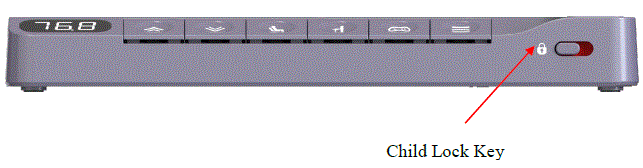
Left switch  button: child lock is on, all keys are locked, the manual end displays “LOC” button: child lock is on, all keys are locked, the manual end displays “LOC”
Right switch |
The memory parameters are listed below:
| Save Parameter | Range | Reset clear Yes/No |
| Current altitude | 72~118 (cm) | Yes |
| Sitting position memory height | 72~118 (cm) | No |
| Standing position memory height | 72~118 (cm) | No |
| Game memory height | 72~118 (cm) | No |
System par ammeter setting screen
| Button Icon | Functional description |
|
Long press the Menu page operation: Under the P0x page, Short press the Parameter setting page operation: In the parameter setting page, press the key to confirm the setting, and then return to the menu page. No operation timeout 5 seconds automatically exit the menu mode and set and save the confirmed parameters Parameter setting page operation: In the parameter setting page, short press the key |
The following figure describes the system parameters:
| Variable name | Menu Number | Range Value | default | notes |
| Display unit | P00 | 0/1 | 0 | 0:Metric untick)
1:Imperial unit inch) |
| Minimum height | P01 | Bottom~ (Top-10) | Bottom | range:Bottom~(Top-10)cm, step size 1cm At the same time, the setting value should be at least 10cm smaller than the maximum limit height value |
| Maximum height | P02 | (Bottom+10)~ Top | Top | range:(Bottom+10)~Top cm,step size 1cm At the same time, the setting value should be at
least 10cm bigger than the minimum limit height value |
| Foundation height | P03 | 0~60 | 0 | Reserved item |
| Ascent resistance sensitivity | P04 | 0~10 | 5 | Protection against rising obstacle: 0:off;1~10:The higher the number, the lower the sensitivity. |
| descent resistance sensitivity | P05 | 0~10 | 5 | Protection against descending obstacle: 0:off;1~10:The higher the number, the lower the sensitivity. |
| Buzzer control switch | P06 | 0/1 | 1 | 0:Turn off the buzzer(Not turn off the abnormal alarm tone) 1:turn on the buzzer |
| Gyroscope alarm switch (optional) | P07 | 0~3 | 0 | 0:Turn off; 1:Small dip angle 2:medium dip angle 3:Big dip angle
After the gyroscope function is enabled, reset the gyroscope. |
| Gyroscope distress sensitivity (optional) | P08 | 0~10 | 5 | Protection function in case of obstacles
0:Turn off;1~10:The higher the number, the lower the sensitivity. |
Energy-saving mode
No operation on the key within 10 seconds, the energy saving mode is entered. The manual display is turned off and the controller enters the low power consumption mode. Press any key to exit the energy saving mode. In energy saving mode, the key motion command does not take effect.10.
Thermal protection
In order to better protect the motor, the system will run 5 meters in 18 minutes, and the system will enter the thermal protection mode. The thermal protection needs to be detected in the shutdown state, and the display screen will display HOT. At this time, other functions of the manual controller will be turned off and the key cannot be used. After 18 minutes, the hand controller will automatically exit the thermal protection mode, or exit the thermal protection mode after power failure and restart.
Automatic test mode
Only the automatic test on the app is turning on the automatic test mode can be started by pressing the button, as shown figure 1. Click the open icon:
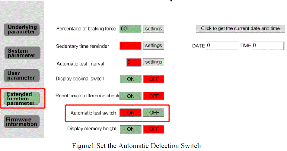
Extended function parameter
| Button Icon | Functional description |
| “”+
“ |
Enter automatic test mode: After the extension function switch is enabled
on the host, press “ Exit Automatic test mode: In the test mode and stopped state, press “ |
| Short press
|
Downtime setting range: 4, 6, 8, 10, 12, 14, 16, 18, 21, 25 minutes
(default: 18 minutes) After 20 seconds, automatically leave this step to enter the test (after which the step no longer supports downtime Settings). |
| Long press
|
Display switch: Switch order, height -> Speed -> Run times three digits
-> Run times three digits low -> Height. After a round trip, the speed display automatically switches back to the height display. |
Gyroscope function
Before using the gyroscope, start the gyroscope function through the upper computer, as shown in Figure 2:
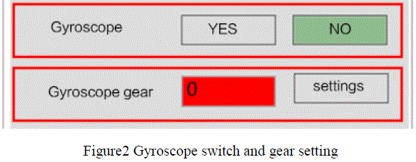
Unbalance alarm
Gyroscope tilt alarm function, you can use the menu P07 to set 1 ~ 3 alarm deviation height, if it exceeds the set deviation report E09. Note: After the gyroscope function is turned on, please perform a reset operation to calibrate the gyroscope.
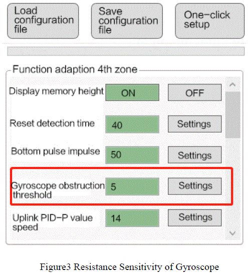
Distress Judgment
Distress sensitivity gear adjustment can be set by the upper computer, as shown in Figure 3. The smaller the gear value, the more sensitive it is. Alternatively, it can be set using menu P08 (see Menu Settings).
Low battery alarm, battery replacement
When the system runs for a long time and the battery is low, the low battery alarm will be activated. At this time, the long lamp will flash once every 2s to remind the user to replace the battery. Please open the battery cover at the bottom of the controller to take out the old battery and put it into two new AAA batteries. At this time, the controller Nixie restores the display height, and then install the battery cover to the bottom of the controller. (Note: Replacing the battery will not affect the connection between the controller and the control box)
Fault codes are list below
When there is a fault, you will hear two Beep sound to remind that the machine is in a fault state and cannot be used. After the fault is completely cleared, you will hear two beep sound to remind that it can be used normally.
| Fault code | Description | Solutions |
| E01 | Motor 1 disconnected | After detecting that there is no problem with the circuit, press and hold the down key for 5s to reset or power off and restart. |
| E02 | Motor 2 disconnected | After detecting that there is no problem with the circuit, press and hold the down key for 5s to reset or power off and restart. |
| E03 | Motor 1 overcurrent | After detecting that there is no problem with the circuit, press and hold the down key for 5s to reset or power off and restart. |
| E04 | Motor 2 overcurrent | After detecting that there is no problem with the circuit, press and hold the down key for 5s to reset or power off and restart. |
| E05 | Hall wire of motor 1 is not inserted | After checking the line is correct, plug in the Hall interface again. |
| E06 | Hall wire of motor 2 is not inserted | After checking the line is correct, plug in the Hall interface again. |
| E07 | Reservation | |
| E08 | Encounter an obstacle | If face abnormal resistance, check whether there is an obstacle.
If the sensitivity is not appropriate, please adjust the sensitivity by referring to the menu section. |
| E09 |
|
If the position deviation on both sides of the table frame alarm, after detecting the line is no problem, long press the down button for 5s to reset
or power off and restart. When the gyroscope detects tilt alarm, the controller will automatically eliminate it after leveling. Or reset to eliminate. |
| E10 | High voltage | Check whether the power supply is correct. If there is no problem, press
and hold the down key for 5s to reset or power off and restart. |
| E11 | Low voltage | Check whether the power supply is correct. If there is no problem, press and hold the down key for 5s to reset or power off and restart. |
| E14 | Overload protection | Check whether the power supply is correct. If there is no problem, press and hold the down key for 5s to reset or power off and restart. |
| E15 | Communication failure |
|
FCC warning
Any changes or modifications not expressly approved by the party responsible for compliance could void the user’s authority to operate the equipment.
This device complies with Part 15 of the FCC Rules. Operation is subject to the following two conditions:
- This device may not cause harmful interference, and
- This device must accept any interference received, including interference that may cause undesired operation.
This transmitter must not be co-located or operating in conjunction with any other antenna or transmitter.
Note: This equipment has been tested and found to comply with the limits for a Class B digital device, pursuant to Part 15 of the FCC Rules. These limits are designed to provide reasonable protection against harmful interference in a residential installation. This equipment generates, uses, and can radiate radio frequency energy, and if not installed and used in accordance with the instructions, may cause harmful interference to radio communications. However, there is no guarantee that interference will not occur in a particular installation. If this equipment does cause harmful interference to radio or television reception, which can be determined by turning the equipment off and on, the user is encouraged to try to correct the interference by one or more of the following measures:
- Reorient or relocate the receiving antenna.
- Increase the separation between the equipment and receiver.
- Connect the equipment into an outlet on a circuit different from that to which the receiver is connected.
- Consult the dealer or an experienced radio/TV technician for help.
This device complies with FCC radiation exposure limits set forth for an uncontrolled environment. This device should be installed and operated with minimum distance 20cm between the radiator & your body.
Documents / Resources
 |
C AND D CL112A Height Adjustable Table Control [pdf] Instruction Manual CL112A Height Adjustable Table Control, CL112A, Height Adjustable Table Control, Adjustable Table Control, Table Control, Control |


