Bricodex V2 Invisible Switch Electric Devices Touchless Control
Product Information
Specifications:
- Product Name: proxiSwitch v2
- Function: Invisible switch for touchless control of electric devices
- Input Voltage: 12-24V DC
Product Usage Instructions
Installation Basics:
Before installation, ensure to disconnect the supply voltage circuit. Mount the controller in a place protected from adverse environmental conditions and third-party access. Follow these steps:
- Disconnect main voltage.
- Mount the device in a stable position.
Connection Diagrams:
Refer to the connection diagrams for connecting to a 12-24V DC device or an LED strip. Follow these steps:
- Connect power wires: (+) and (-).
- Connect the LED strip, paying attention to polarity.
- Clean and dry the surface before adhering the controller.
- Adhere the device to a non-conductive surface.
Calibration:
The device performs auto-calibration within the first 15 seconds after power connection. Avoid placing conductive objects near the device during this process.
Control:
To control the LED strip, close your hand to the controller. The device operates in four modes:
- Bistable without memory
- Bistable with memory
- Monostable NO
- Monostable NC
Changing Operating Mode:
To change the operating mode, follow these steps:
- Turn on the power.
- Wait for the LED to start flashing.
- Immediately disconnect the power.
Frequently Asked Questions (FAQ)
- Q: How do I reset the device if it reacts incorrectly?
A: Force auto-calibration by disconnecting and reconnecting the power supply to the controller. - Q: What should I do if the device does not work properly?
A: Ensure the device is stably fixed on a non-conductive surface and not near metal elements. Re-adhere if necessary.
SAFETY RULES
![]() Do not connect the device to loads exceeding the permitted values.
Do not connect the device to loads exceeding the permitted values.
![]() Connect only in accordance with the diagram presented in the manual. Improper connections may be dangerous, it can damage the controller, and loss of the warranty.
Connect only in accordance with the diagram presented in the manual. Improper connections may be dangerous, it can damage the controller, and loss of the warranty.
 DANGER! Risk of electric shock! Even with the device turned off, the outputs may be live. All assembly work should be ALWAYS performed with the disconnected power circuit.
The installation of the device to a power mains that does not meet the quality requirements defined by EN 50081-1, EN 50082-1, UL508, EN 60950, will result in the loss of the warranty.
INSTALLATION – BASICS
- Disconnect supply voltage circuit before installing the controller. Remember that any mounting works should be carried out when the main voltage is disconnected (switch off the mains fuse or disconnect the power supply from the socket).
- The controller should be installed in a place protected against adverse environmental conditions, protected from third party access. It is recommended that the device be mounted in a stable and fixed position.
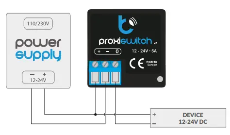
CONNECTION DIAGRAMS
General diagram of connection to the 12-24V DC device:
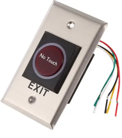
 Touch button – proxiSwitch + switchBoxDC:
 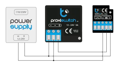 General scheme of connection to the LED strip 12-24V DC:
 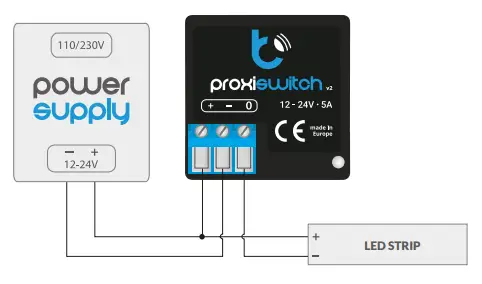 Touch button – proxiSwitch + wLightBoxS:
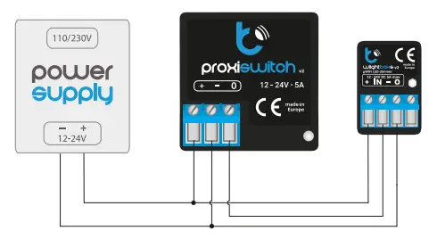
- Familiarize yourself with the diagram and then proceed with the installation of the controller. Pay special attention to the designation of the controller connectors. Start by connecting the power wires: (+) (red or black with a white dotted line) and (-) (black).
- Connect the LED strip (paying attention to the polarity). The device is equipped with two stripes of double-sided adhesive tape on the bottom side. Before sticking the controller, clean and dry the the surface where it will be adhered. Remove the protective film, adhere in the chosen place and hold for a few seconds. When choosing the mounting location, remember that the device detects the hand only from the side of the adhesive tape.
The device should be adhered to a non-conductive surface, eg furniture board, tile, etc. If the device is not stably fixed or mounted near metal elements, it may not work properly. 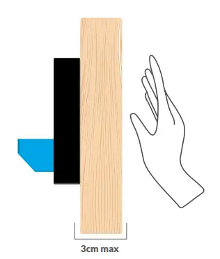
- Each time the power source is connected, the device performs the auto-calibration process within the first 15 seconds. During this time, do not place your hand or any conductive objects near the device, as this will affect the calibration process.
If during the normal operation the device reacts incorrectly, force the auto-calibration process by disconnecting and reconnecting the power supply to the controller. Remember that after connecting the power supply do not put your hand near the controller for the first 15 seconds!
CONTROL
- To turn on / off the LED strip, close your hand to the controller.
The device can operate in four operating modes:
- bistable without memory – after switching on the power supply, the output is switched off, each time you close your hand, the output changes. When the power supply is disconnected and reconnected, the output will always be off.
- bistable with memory – after switching on the power supply, the output state depends on the state before the power loss (the last state is remembered 5 seconds after its last change). Each time you close your hand, the output state changes.
- monostable NO – after turning on the power, the output is in off state. It turns on when you close your hand.
- monostable NC – when the power is turned on, the output is also on. It turns off when you close your hand.
To change the operating mode of the device, follow the steps below:
- turn on the power, wait 5 seconds until the LED starts flashing; immediately disconnect the power.
- turn on the power, wait 10 seconds until the LED starts flashing; immediately disconnect the power.
- turn on the power, wait 15 seconds until the LED starts flashing; immediately disconnect the power.
- turn on the power. Select the mode by placing your hand close the controller. Each time you close your hand, the number of LED flashes indicates the selected mode.
- wait 10 seconds after the last movement until the LED starts flashing; immediately disconnect the power.
- after reconnecting the power supply, the device start to work in the newly selected mode.
TECHNICAL SPECIFICATIONS
| supply voltage | 12–24V DC |
| energy consumption | <0,1W |
| maximum current | 5A |
| maximum power | 120W |
| status signaling | blue diagnostic LED |
| modes | bistable, bistable with state memory, monostable NO, monostable NC |
| detection range | depending on the material: plexiglass, solid wood, plywood, chipboard – 3cm, metal – detection with the entire surface, honeycomb panels – no detection |
| maximum detection time in monostable mode | 8 sec |
| autocalibration | at startup and every 15 seconds |
| sensor | proximity, capacitive sensor |
| mounting method | under the surface of nonconductive, adhesive tape |
| housing | made of polyurethane composition not containing halogens, self-extinguishing for thermal class B (130 °C) |
| dimensions | 38 x 38 x 19 mm |
| protection level | IP20 |
| controller operating temperature | from -20 to + 50°C |
ADDITIONAL INFORMATION
HELP
- The latest versions of the manual, additional informations and materials about products are available on our website: blebox.eu
- General questions: info@blebox.eu
- Service and technical support: support@blebox.eu for more information visit our website www.blebox.eu or send us an email to: info@blebox.eu support is available at support@blebox.eu
made in Europe
 DISTRIBUTED BY Wired 4 Signs USA
+1 (865) 339 4956 info@w4susa.com
7669 Clinton Highway, Powell, Tennessee, 37849 
Documents / Resources
 |
Bricodex V2 Invisible Switch Electric Devices Touchless Control [pdf] User Manual V2 Invisible Switch Electric Devices Touchless Control, V2, Invisible Switch Electric Devices Touchless Control, Electric Devices Touchless Control, Devices Touchless Control, Touchless Control |


