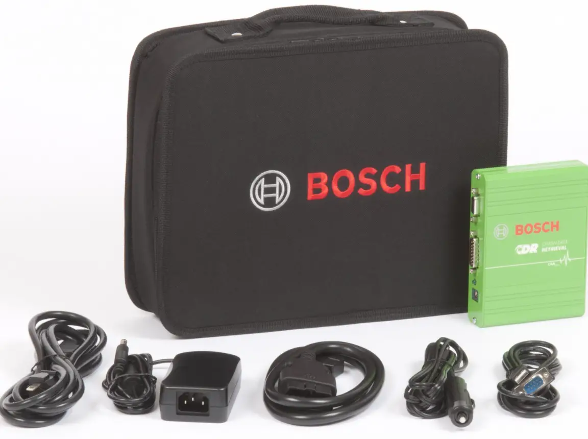
BOSCH VDC01 Visual Data Collection Kit
Specifications
- Product: Visual data collection kit
- Manufacturer: Bosch
- Main Components: Collection ECU, Collection CAM
Product Information:
The visual data collection kit is designed for collecting visual data of specific traffic scenarios to train artificial intelligence algorithms used in vehicle-related technologies. It consists of the Collection ECU and Collection CAM for image capture and processing.
System Description:
Vehicle manufacturers and suppliers, like Bosch, aim to enhance the reliability and speed of AI technologies in vehicles. The system captures images of traffic scenarios to train AI algorithms for appropriate responses.
General Use:
- Activating the system: Follow the instructions provided to power on the system.
- Resetting the system: To reset the system, refer to the user manual for detailed steps.
- ECU and CAM LEDs: Monitor the ECU and CAM LEDs for system status indications.
- Using the system: Ensure proper installation and connection of components for effective data collection.
QR codes
- QR code 1
 https://bosch-visual-data-collection.com
 - QR code 2
 https://bosch-visual-data-collection.com/inst4V2
 - QR code 3
 https://bosch-visual-data-collection.com/um4V2
 - QR code 4
 https://bosch-visual-data-collection.com/webApp
 - QR code 5
 https://bosch-visual-data-collection.com/video
 - QR code 6
 https://bosch-visual-data-collection.com/remove
 - QR code 7

https://bosch-visual-data-collection.com/status-webapp - QR code 8
 https://bosch-visual-data-collection.com/wfp4V2
Important information
- The visual data collection kit, all components, and the system package remain the property of Bosch and must be returned to Bosch after use. Do not dispose of any components or packaging materials as waste; all components must be returned to Bosch in the system package.
System description
- One of the most important tasks of vehicle manufacturers and suppliers, such as Bosch, is to increase the reliability and speed of vehicle-related technologies that use artificial intelligence (AI).
- An important step in this direction is to train the AI algorithms based on real traffic data so that they can react appropriately, especially in critical situations.
- The visual data collection kit (hereafter referred to as the “system”) identifies specific traffic scenarios, captures images, and sends them to Bosch.
- The cataloged images are processed using an algorithm that defines the necessary vehicle response. Better algorithm training improves the detection of similar situations, enabling corresponding measures to be initiated more reliably in subsequent phases.
- The system consists of two main components: the collection ECU (hereafter referred to as the “ECU”, refer to figure 2) and the collection cam (hereafter referred to as the “CAM”, refer to figure 3). To allow the ECU and the CAM to communicate, these components must be connected using the camera connection cable (refer to item [7] of figure 1) during system installation.
- The ECU performs trigger-based data acquisition, meaning that it selectively collects data as defined by Bosch, rather than constantly recording and transmitting data.
- The CAM captures image data with its high-resolution camera head. The image data captured by the CAM arethen digitally transferred to the ECU, which in turn transfers the data to the secure Bosch RideCare cloud via a 4G wireless connection.
- The system’s 4G connectivity also allows over-the-air updates of its firmware, software, and parameters.
- This user manual does not contain installation instructions and assumes that the system has been properly installed, activated, and calibrated. Refer to the installation instructions for full instructions on installing, activating, and calibrating the system. Scan the QR code to download the installation instructions:

https://bosch-visual-data-collection.com/inst4V2
- Refer to the deinstallation instructions to remove the entire system after use. Scan the QR code for the deinstallation information:

https://bosch-visual-data-collection.com/remove.
- Please follow the instructions in this manual to use the system safely and obtain optimal results. We also recommend keeping this manual handy for future reference. This manual applies to part number 7 507 650 603. Make sure to read through all safety-related information before using this system.
- Check the online version of this manual to ensure that you are referring to the latest information. Scan the QR code to download the user manual:

- https://bosch-visual-data-collection.com/um4V2
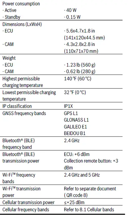
Specifications
Category Specification
- Operating temperature 14°F to 140°F (-10°C to +60°C)
- Storage temperature -4°F to 185°F (-20°C to +85°C)
- Relative operating humidity 20% to 80% non-condensing
- Input voltage +8 V DC to +32 V DC (nominal +12 or +24 V DC)
Safety instructions
- Read and save these instructions.
Explanation of symbols
- WARNING
- Indicates that serious or life-threatening injury may occur.
- NOTICE Indicates that material damage may occur.
Safety-related warnings
- WARNING: The lithium-ion battery inside the ECU is classified as a hazardous material. For shipment, the components must be packaged in a certified dangerous goods package, i.e., the system package. For this reason, the system package must not be disposed of and must be stored in such a way that it can be used to return the system to Bosch after use. WARNING Before shipping the system back to Bosch shipping mode must be activated. To do so, unplug the collection car charger (hereinafter referred to as the “car charger”) from the 12 V power socket and perform five short presses of the ECU multifunction button (refer to item [10] of figure 2). Both LEDs will flash red for three seconds to indicate that the system is entering shipping mode. Then all LEDs will go out.
- WARNING: Read and follow the instructions and precautions in this manual and all documents referenced in this manual when installing this system. Always refer to the vehicle manufacturer’s service manual for proper installation and wiring of any aftermarket devices, including this system. Failure to do so may result in property damage and/or personal injury.
- WARNING: Do not hit an installed CAM forcefully for any reason as this could crack the windshield.
- WARNING: Do not press too hard on the windshield from the inside of the vehicle when installing the CAM, as this could cause the windshield to pop out.
- WARNING: When installing the CAM, the connection cable (item [7] of figure 1) must be fixed with a cable clip (item [23] of figure 1) near the CAM on the windshield. This prevents the cable from detaching from the CAM in the event of an impact or vibrations. Further details are included in the installation instructions (QR code 2).
- WARNING: Do not use spot heating (e.g., a heat gun) to remove components from the windshield as this could crack the windshield.
- WARNING: Do not use metal tools (e.g., metal scrapers) to remove components from the windshield as this could scratch the windshield. Use only the plastic tool provided.
- WARNING: To avoid injury, do not look directly at the status LEDs located on the ECU or CAM from a distance of less than 7.9 in (20 cm).
- WARNING: Be careful to avoid burns as the CAM or ECU may become warm due to the heat generated during continuous operation and may, therefore, cause minor burns to the driver or passenger. Ensure that the CAM and ECU are installed inside the vehicle. Be aware that external installation exposes the components to external heat and rain/water, leading to either overheating or an electrical failure due to water ingress in devices and adversely affecting vehicle performance.
- WARNING: Failure to avoid the following potentially hazardous situations could lead to an accident or collision resulting in death or serious injury. When installing or using the CAM, ECU, collection remote button (hereafter referred to as the “remote button”), and all corresponding wiring in a vehicle:
- Do not obstruct the driver’s view with any system components or wiring.
- Do not use the system if any components have been installed in front of an airbag or in a position that could interfere with the operation of the vehicle’s airbags.
- Do not use the system if any components are in a location that could interfere with vehicle operating controls.
- Before mounting the CAM on your windshield, check the state/local laws and ordinances where you drive. Some state/local laws prohibit or restrict the placement of objects on the windshield of a motor vehicle.
- It is the installer’s responsibility to mount the CAM in compliance with all applicable laws and ordinances.
- WARNING Secure all cables to prevent injury caused by accidentally pulling on a cable when entering or exiting the vehicle.
General safety instructions
- Important: when mounting the ECU, the installer must ensure that the hook-and-loop tape is sufficient. The hook-and-loop tape mounting option may only be used on a surface that provides it with sufficient grip, e.g., the car carpet.
- Important: if parts of the system are not attached securely enough, they may detach from the car in the event of an accident or impact, potentially hitting the driver or a passenger. To mitigate potential hazards, prioritize safety by ensuring that the ECU is securelyattached. In addition, please also ensure that the CAM is properly installed; refer to the installation instructions for more details. Make sure not to block any vehicle service covers or accesses points (e.g., the cabin air filter behind the glove compartment).
- Important: do not use this system in an environment where the temperature is too high or too low. The operating temperature range of the system is: -10°C to +60°C.
- This system must only be installed inside a streetlegal vehicle with a +12 V DC or +24 V DC electrical system.
- Do not cover any of the vents on the ECU or the CAM. Doing so may cause a buildup of heat in the system, which could cause a malfunction.
- Make sure to check for debris obstructing the ECU vents. Blocked vents may lead to inadequate air flow, resulting in overheating and premature ECU shutdown. Prioritize ensuring that vents remain clear to maintain proper cooling and prevent operational issues.
- Do not kink the camera connection cable between the ECU and the CAM. A minimum bending radius of 40 mm must be observed.
- To remove the camera connection cable between the ECU and the CAM, the locking button on the connector must first be pressed (unlocked).
Disconnecting the connector without unlocking the locking mechanism will destroy the cable’s connector. - To prevent damage to the connector, avoid using excessive force during handling. Avoid the risk of cables loosening due to pulling. Handle cables gently to avoid unintentionally disconnecting or damaging the cables, thereby ensuring the reliability of the connections for optimal performance.
- Some cables have a locking mechanism/locking latch. Make sure to fully depress the locking lever before attempting to remove the cable.
- Do not disassemble the ECU, the CAM, or any other components.
- Do not use the system if it or any of its components seem damaged.
- Do not insert foreign bodies into the openings on the ECU or the CAM – otherwise personal injury or damage to the device may occur.
- Do not bring hot or burning objects (e.g., cigarettes, heat gun, etc.) into contact with the ECU or the CAM.
- Ensure proper installation to avoid misalignment issues, particularly when adjusting the angle of the CAM on the windshield. Make sure that the vehicle is parked on level ground before installing the CAM.
Check that the CAM is correctly positioned horizontally by using the spirit level in the collection cam mounting frame cover (hereafter referred to as the “CAM mounting frame cover”, refer to item [10] of figure 1). A misalignment may compromise system functionality. Refer to the installation instructions for more details (QR code 2). - To avoid damaging the CAM, use only the adjustment tool provided (refer to item [15] of figure 1). Do not exceed the specified angle limits (refer to the position arrows on the angle indicator dial on the left CAM side, item [4] of figure 3) to ensure proper functioning and prevent any damage to the gear mechanism.
- Do not install the same collection cam mounting frame (hereafter referred to as the “CAM mounting frame”) twice. For repeated installation, the self-adhesive glue pad must be replaced, or a new CAM mounting frame must be used.
- When cleaning the CAM, never use hard or sharp objects that could damage the protective lenses or housing.
- Do not use aggressive cleaning agents such as thinners, benzine, abrasive cleaners, spray cleaners, acidic or alkaline solutions, or wax to clean the ECU, the CAM, or the optical surfaces of the camera.
- Note that improperly installing the CAM lens hood on the windshield may result in insufficient image quality. Ensure that the lens hood is correctly and securely installed to maintain consistent image quality. Please refer to the installation instructions for more detailed information (QR code 2).
- The ECU must be mounted in the passenger area below waist height to minimize the risk of injury in the event of an accident.
- Ensure that the ECU has not been installed in a location that is prone to accidental spillage of liquids. If the ECU comes into contact with any liquids, the power supply must be disconnected from the system immediately by unplugging the car charger. Also unplug the CAM from the ECU. Use a clean, dry cloth to wipe any exposed surfaces dry.
Inspect the ECU for any liquid that may have entered its enclosure. If liquid is present inside the ECU, leave the car charger unplugged and contact visual.data.collection@bosch.com. - If the enclosure appears to be free of liquid, plug the car charger back in and press and hold the ECU multifunction button (item [10] of figure 2) for at least three seconds to reactivate the system. If the system does not reactivate, unplug the car charger and contact visual.data.collection@bosch.com.
- Refer to section 6.1 Activating the system.
- Do not spray any liquids onto the ECU or the CAM. Make sure that no liquid enters these component
- Do not become distracted by the CAM, the remote button, your smartphone, or any other device while driving, and always be aware of all driving conditions.
- Ensure that the lens is not obstructed in any way.
- Before operating the vehicle, ensure that the lens hood is firmly and securely affixed to the CAM mounting frame according to the installation instructions.
- Ensure that the lens hood is not obstructing the driver’s view through the windshield.
- Do not operate the vehicle if the lens hood is not firmly and securely affixed to the CAM mounting frame according to the installation instructions.
- Users may not dispose of the system: this system and its batteries may contain hazardous substances that could impact health and the environment if not disposed of properly.
- Observe the local and national regulations that apply where this system is in use. Use of this system may be restricted in some countries, states, or regions.
- The system always remains the property of Bosch and must be returned to Bosch after use.
- Do not use the system if any of its components appear damaged.
- Please contact the visual data collection support team for the return procedure: visual.data.collection@bosch.com.
Important instructions
- Camera legal notice: In some jurisdictions, it could be considered an invasion of privacy rights to take or publicly display photographs or videos of people or their vehicles using this product. It is your responsibility to know and comply with the laws and rights to privacy that apply in your region.
- In compliance with local laws and regulations governing video and audio recordings, as well as obtaining the necessary consent, it is mandatory to clearly mark the vehicle on all four sides using the removable recording notice stickers provided (item [4] of figure 1). Some jurisdictions may have specific requirements, and to assist with compliance, we include this sticker for display on your vehicle. To ensure your safety and compliance with data privacy legislation, it is imperative that such requirements are always met.
- None of the information in this manual is legal advice. If you have any questions about the law, please consult an appropriate legal professional.
- In certain situations (e.g., when driving through a sensitive area that does not allow image capture), the CAM may need to be temporarily removed from its mounting frame. Refer to 5.3 CAM, section Temporarily removing the CAM from the windshield.
- When handling the CAM, ensure that it is not dropped or exposed to any shocks, as this could damage its image sensor. Also, ensure that the lens is not touched or exposed to dirt, debris, or liquids as this could decrease the quality of the images captured.
- Ensure that the ECU and the CAM are properly installed before operating your vehicle.
- To access the installation instructions, refer to QR code 2.
Installation package contents
Legend of figure 1.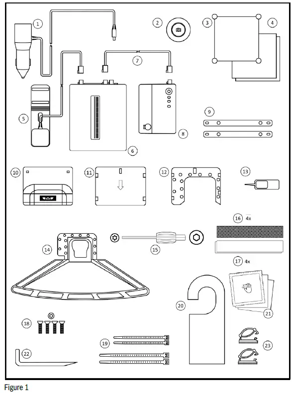
- Collection car charger
- Collection remote button (optional)
- QR code sign with suction cups
- Car stickers in black and white
- External antenna
- Collection ECU (ECU)
- Camera connection cable
- Collection cam (CAM)
- ECU mounting plates
- CAM mounting frame cover
- CAM lens cover
- CAM mounting frame
- Reset tool
- Lens hood
- Adjustment tool
- Hook-and-loop tape
- Mushroom-head fastener tape
- Screws
- Cable ties
- Mirror flyer
- Alcohol wipes
- CAM removal tool
- Cable clips
Not included in package: Smartphone (iOS or Android)
- If you need any replacements or spare parts, please contact visual.data.collection@bosch.com.
- For more information on the main system components, please refer to the next section.
System components
- Collection ECU 7 507650 603
- Collection cam 0220M00095
- Collection cam mounting frame 0220M0006M
- Lens hood 1a 0220M999A9
- Lens hood 2a 0220M99993
- Lens hood 3a 0220M99994
- Collection remote button 7 507650 607
- Collection car charger 7 507650 611
- Camera connection cable 0950A2219L-B03
- External antenna 0790A2219L-A03
ECU
- The ECU is one of the two main components of the system. It performs central computing, processing and transmission of the image data. It also supplies power to the CAM, which is mounted on the windshield.
Legend of figure 2.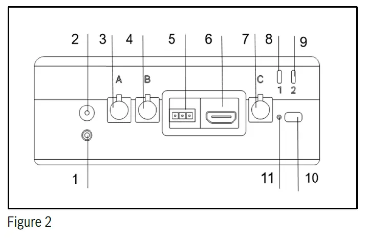
- Retaining screw
- Power input
- Camera connector A
- Camera connector B
- CAN service port
- HDMI service port
- GNSS antenna port C
- LED 1
- LED 2
- Multifunction button
- Reset button (in pinhole)
- ECU contains an internal, rechargeable lithium-ion battery used to power the system during short-term interruptions in vehicle power. Failure to follow the instructions below may decrease the service life of the ECU’s battery or cause a risk of damage to the device, fire, chemical burns, an electrolyte leak, and/or injury.
- Use only the provided car charger to power the ECU.
- Do not expose the ECU or its battery to a heat source.
- Do not puncture or incinerate the ECU or its battery.
- When storing the ECU for longer than three months, make sure that the battery is charged and store it within the temperature range from 68°F to 86°F (20°C to 30°C).
- Do not attempt to replace the ECU’s internal battery.
- Do not expose the ECU to extremely low air pressure as this could result in an explosion or the leakage of flammable liquid or gas
CAM
- The CAM is one of the two main components of the system. Its camera head produces high-resolution images.
Legend of figure 3.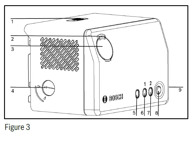
- Camera lock switch
- Camera angle lock screw
- Camera angle adjustment screw
- Camera angle indicator
- Ambient light sensor (ALS)
- LED 1
- LED 2
- Multifunction button
- ECU cable connector
- The CAM has a single exterior-facing camera with a wide-angle lens covering a large viewing area. Take care not to obstruct the lens.
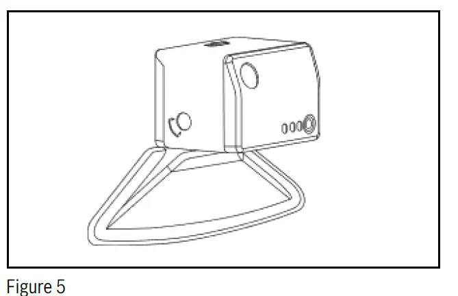
- Following system installation, the CAM will be secured to the vehicle’s windshield in a position and angle allowing optimum system performance. The CAM uses a lens hood (refer to figure 5) to reduce glare and capture the best possible images. Lens hood options are provided to ensure the optimal fit to the windshield of a specific vehicle type (van, truck, passenger car).
- The back of the CAM features an ambient light sensor (ALS), two multicolor LEDs, and a multifunction button to display the system status and allow system activation.
- Refer to items [5], [6], [7], and [8] of figure 3.
- The brightness level of the two status LEDs is automatically adjusted according to the ambient lighting conditions as detected by the ALS. Always ensure that the ALS is clean and not obstructed in any way so that the ambient lighting conditions can be measured accurately.
- For detailed information on using the device button and interpreting the status LEDs, please refer to sections 6.1
- Activating the system and 6.3 ECU and CAM LEDs.
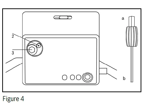
- The CAM includes a camera angle adjustment screw, camera angle lock screw, and a camera angle indicator dial – refer to items [2], [3], and [4] of figure 4.
- After mechanical installation of the ECU and the CAM, the system must be calibrated using the web app provided. For detailed calibration instructions, please refer to the installation instructions provided. To download the latest installation instructions, refer to QR code 2.
- The lens angle must be mechanically adjusted by using the screwdriver end (a) of the provided adjustment toolto turn adjustment screw [3] and by referring to the installation user interface on the smartphone. Refer to figure 5.
- The lens angle must be mechanically adjusted by using the screwdriver end (a) of the provided adjustment toolto turn adjustment screw [3] and by referring to the installation user interface on the smartphone. Refer to figure 5.
- After adjusting the lens to the optimal position (refer to QR code 2), the lens mechanism must be locked by using the screwdriver end (b) of the adjustment tool to turn lock screw [2]. Screw [2] must be tightened hand tight. Refer to figure 5. Failure to follow these instructions will lead to the lens adjusting incorrectly during the operation of the system.
Temporarily removing the CAM from the windshield
To remove the CAM from the windshield temporarily, follow these instructions: - Remove the connecting cable from the CAM.
- Unlock the CAM using the CAM lock switch (refer to item [1] of figure 3) and detach the CAM from the CAM mounting frame by sliding the CAM upwards and then taking it off.
- Fit the CAM lens cover (refer to item [11] of figure 1) to protect the CAM lens and stow it away safely.
- Fit the CAM mounting frame cover (refer to item [10] of figure 1) onto the CAM mounting frame and attach the connecting cable to the cover.
CAM lens cleaning instructions
- If the CAM lens requires cleaning, please follow these instructions.
- Important: The CAM must be detached from the CAM mounting frame before cleaning.
- Important: The ingress of detergent into the CAM must be avoided.
- To clean the surface of the front lens, use lens cleaning wipes with clean 99.5% isopropyl alcohol.
- Wipes that have been soaked in high-percentage clean isopropyl alcohol may also be used to clean the CAM lens.
- Do not underestimate the risk of degraded image data quality caused by lens scratches, smudges, or dirt accumulation. Avoid touching the lenses when mounting the CAM on the windshield. Handle lenses with care to ensure optimal performance.
- Before installation, the user must detach the CAM mounting frame cover (refer to item [10] of figure 1) and affix the CAM mounting frame. If it is necessary to handle the CAM, protect the lens using the collection cam lens cover (hereafter referred to as the “CAM lens cover”, refer to item [11] of figure 1) whenever the camera is not in use. When installing the CAM for the first time, check the cleanliness of the lens.
CAM mounting frame
- The CAM mounting frame (refer to item [12] of figure 1) is permanently mounted on the windshield of the vehicle. It is the interface to the lens hood, which is also permanently mounted on the windshield.
- The CAM mounting frame is also the interface to the CAM and allows the CAM to be mounted on and detached from the windshield.
- WARNING: The CAM mounting frame features protruding sharp-edged hooks for mounting the CAM. In the event of an impact, they can cause severe head injuries. Therefore, when the CAM is not attached to the windshield, the CAM mounting frame must be covered with the provided CAM mounting frame cover to prevent passenger injury in the event of an accident.
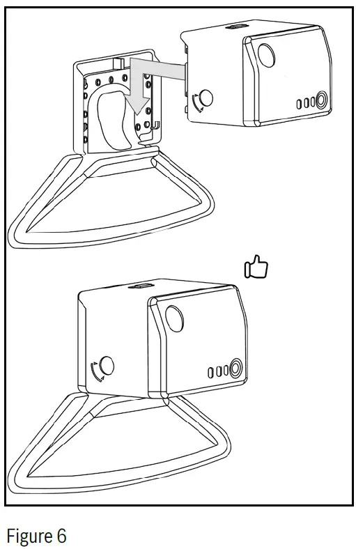
- The CAM mounting frame cover (containing the small spirit level) must be slid onto the CAM mounting frame from the top and must be properly seated on the CAM mounting frame (refer to Figure 6).
Car charger
- The system is installed with the car charger, which powers the system and charges the ECU backup battery whenever vehicle power is available.
Legend of figure 9.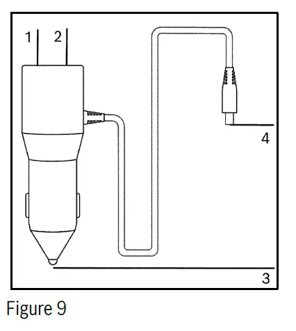
- USB A port (5 V DC/1.5 A)
- USB C port (5 V DC/3.0 A)
- To vehicle power
- To ECU power input
- The car charger is connected to the vehicle’s +12 V … +24 V DC power port (cigarette lighter socket) at one end and to the ECU’s power input connector at the other end. Refer to items [3] and [4] of Figure 9.
- Carefully tighten the retaining screw on the round hollow connector on the ECU (refer to item [1] of figure 2)
using the small end of the provided CAM lens adjustment tool (refer to item [15] of figure 1). - The ECU powers the CAM via the camera connection cable, which connects the two components.
- The car charger includes one USB type C socket (refer to item [2] of figure 9) and one USB type A socket (refer to item [1] of figure 9) that can be used to charge external devices such as smartphones or tablets by connection an appropriate charging cable (not included in the installation package). The car charger’s USB type A and C voltage outputs are fixed at +5 V DC (+/-5%), with a 1.5 A and a 3.0 A fuse, respectively. The car charger USB outputs do not support data transfer.
- WARNING: Make sure to use only the car charger supplied with the system. The use of an unapproved or damaged car charger can have serious consequences.
Remote button (optional) Refer to Figure 7.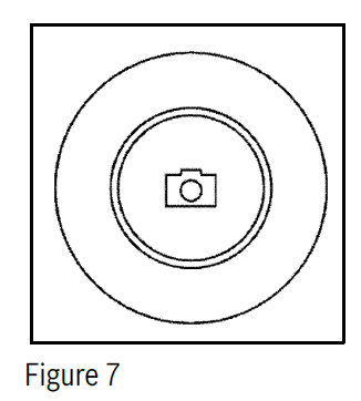
- The remote button is used by the driver to trigger an immediate image capture.
- Note that before using the remote button for the first time, the rectangular pull tab on the side must be removed. This will activate the battery.
- During system installation, the remote button was paired with the ECU (via Bluetooth®). If the remote button becomes unpaired from the ECU, refer to the installation instructions for pairing instructions.
- The remote button is used by simply pressing down on the center button cap, which shows a camera icon.
- There will be an audible clicking sound, and both status LEDs on the CAM will turn yellow for two seconds.
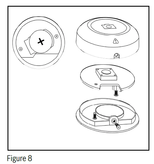
- The remote button is equipped with a coin cell battery (type CR2032). Make sure to read the safety warnings in this manual prior to handling.
- The remote button housing is made up of two parts: a lower part and an upper part. The upper part contains the actual button, as well as the battery. To separate the upper and lower parts, first remove the safety screw (refer to figure 8). Then, twist the upper part counterclockwise independently of the lower part for about an eighth of a turn, or until it cannot rotate any further. The two housing parts can then be easily pulled apart, making the battery holder accessible. To ensure that disassembly is possible, the remote button should be mounted in the vehicle in a position that allows access to the safety screw. Once disassembled, flip over the upper housing part to reveal the battery. Refer to Figure 8.
- WARNING The remote button contains a coin cell battery. If the coin cell battery is swallowed, it can cause severe internal burns in just two hours and can lead to death.
- Do not ingest the battery – risk of chemical burns.
- Keep new and used batteries away from children.
- If the battery compartment does not close securely, stop using the product and keep it away from children.
- If you think a battery may have been swallowed or placed inside any part of the body, seek immediate medical attention.
- Even used coin cells may cause injury.
- WARNING: The remote button emits radiation –in the form of electromagnetic waves, e.g., radiofrequency radiation – in compliance with the FCC and IC RSS-102 radiation exposure limits for uncontrolled environments.
- When installing and operating this equipment, maintain a minimum distance of 7.9 in (20 cm) between the remote button and your body.
- WARNING: Ensure that the remote button is securely attached using the adhesive pad on the back.
- Antireflective velour pad
- In certain cases, it may be necessary to install the anti-reflective velour pad to further reduce reflections in the camera image.
- In these cases, the velour pad will be provided in the package.
- NOTICE: If the black velour pad is provided in the installation package, it must be installed. Please observe the following instructions:
- Make sure the velour pad does not cover the windshield vents. If necessary, make cutouts for the vents or place the velour pad behind the vents. Vents must not be covered up.
- The velour pad must be firmly fixed to the dashboard using the self-adhesive back of the pad. Clean the dashboard of dust and debris, remove the protective film from the back of the pad, align the pad, and firmly press it on. Failure to firmly attach the velour pad can result in dangerous driving conditions (pad blocking the driver’s view).
General use
Activating the system
- The system will power up automatically when it detects an external electric power supply from the vehicle (e.g., when the vehicle starts).
- If the system is installed in a vehicle whose cigarette lighter socket remains powered even when the vehicle is turned off, the camera system will shut down after ten minutes of no movement being detected.
The system may also be powered up manually using the buttons on the ECU (refer to item [11] of figure 2) and the CAM (refer to item [8] of figure 3). These buttons are used to turn the system on or off manually, as described below: - The system can be powered ON by pressing and holding the ECU button [11] for longer than three seconds. If the system is not connected to vehicle power, it will start on battery power. If the battery is not charged and no vehicle power is available, the system cannot start, and the ECU status LED 1 flashes red three times.
- The system can be powered OFF by pressing and holding the multifunction button on either the CAM [8] or the ECU [11] for longer than three seconds.
- An unwanted start of the system can be avoided by shutting down the system manually and removing the car charger from the vehicle’s cigarette lighter socket.
Note that the system will shut down automatically if no vehicle power is present and the ECU battery is empty.
Resetting the system
- The system can be reset (rebooted) by pressing the reset button [11] of the ECU (refer to figure 2).
- Note that this system reset does not restore the system’s factory settings or reconfigure any of the system calibrations established during installation. Once rebooted, the system will continue to operate as installed.
- To reset the system, use the reset pin tool provided (item [13] of figure 1) and press the reset button (item [11] of figure 2) via the pinhole.
- If the system shuts down unexpectedly for any reason, the system must be turned off and on again to reactivate it.
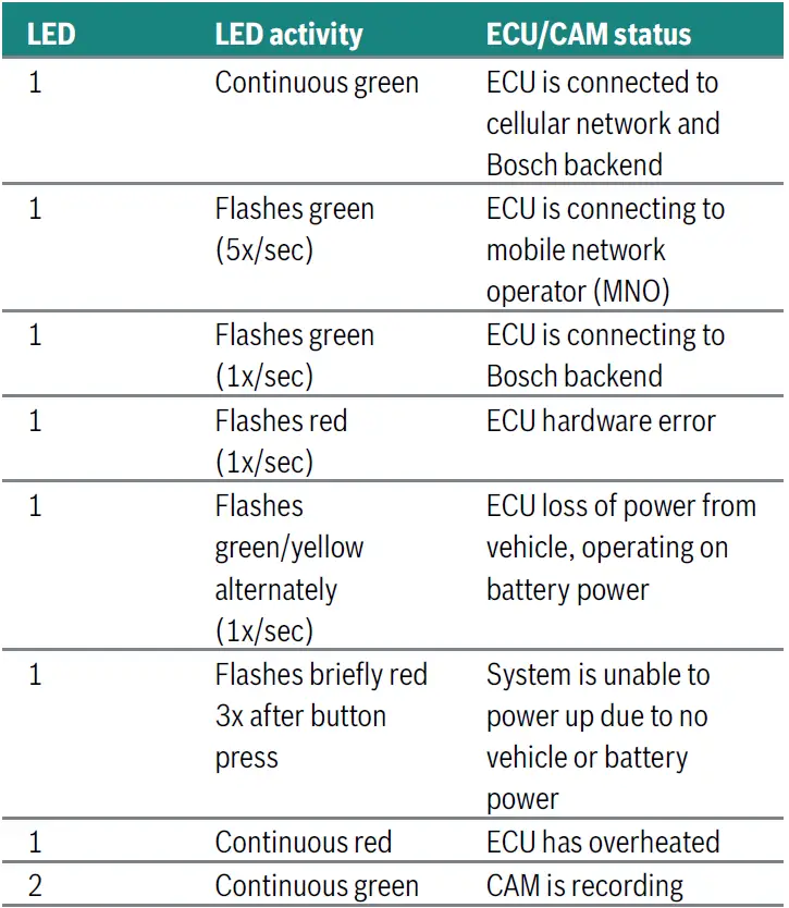
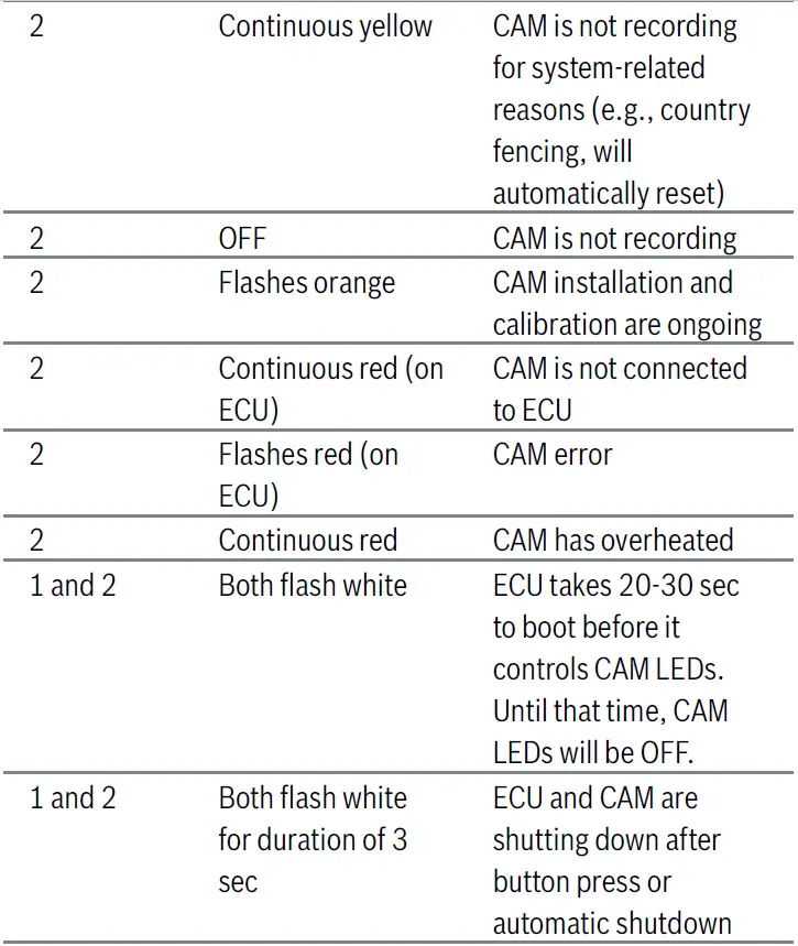
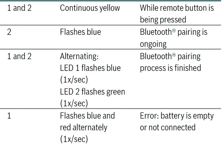
ECU and CAM LEDs
- The CAM and ECU each have two multicolor LEDs to indicate system status. The LEDs on each component are referred to as LED 1 and LED 2. The LED 1 and LED 2 on the ECU provide the same information as their counterparts on the CAM, with LED 1 showing ECU status and LED 2 showing CAM status

- Using the system
- When powered on and connected to the Bosch backend, the system will automatically capture and upload image and location data according to parameters predetermined by Bosch. An immediate capture of data may be initiated by the user by pressing the remote button (refer to section 5.6 Remote button (optional)). If the system has not automatically powered on and connected, refer to section 6.1 Activating the system, for manual activation instructions.
- Before use, ensure that the system has been installed, activated, and calibrated according to the installation instructions. Refer to the installation instructions (QR code 2) for detailed instructions.
- For more details on product usage, refer to the visual data collection website (QR code 1).
- Important: all services will only be available when the device is on. This includes use of the remote button and the quick upload feature.
Glossary
Ambient light sensor | ALS
- Automatically controls the brightness level of the LEDs according to the ambient lighting conditions. Do not cover.
Camera connection cable
- Connects the collection ECU and the collection cam.
Collection cam | CAM
- One of the two main components of the visual data collection kit. Its camera head produces high-resolution image data.
Collection cam lens cover | CAM lens cover
- Needs to be installed on the front of the collection cam whenever the collection cam gets detached from the collection cam mounting frame to avoid lens damage.
Collection cam mounting frame | CAM mounting frame
- The collection cam mounting frame is permanently mounted on the windshield. It serves as an interface to allow the collection cam to be mounted on and detached from the windshield.
Collection cam mounting frame cover | CAM mounting frame cover
- Needs to be clipped onto the collection cam mounting frame whenever the collection cam is removed from the frame. Covers the frame to avoid injuries and serves as an installation aid.
Collection car charger | car charger
- Power supply for the visual data collection kit. It should be permanently connected to the +12 V … 24 V DC vehicle power socket.
Collection ECU | ECU
- One of the two main components of the visual data collection kit. Performs central computing, processing and transmission of the image data.
Collection remote button | remote button
- Optional component connected via Bluetooth®. It can be used by the driver to trigger an immediate image capture.
Component identification label | label
- Label on a component providing identification and registration information.
Connector
- A connector links a cable and a component. A connector can be plugged into a socket.
Hook-and-loop tape
- For mounting the collection ECU on surfaces such as the vehicle carpet.
Installation instructions
- Illustrated step-by-step installation instructions. The print version is included in the installation package. PDF version available online. Refer to QR code 2.
Installation package
- The package in which all the required components are delivered refer to Figure 1.
LED
- LEDs on the collection ECU and collection cam.
LED flashes green (5x/sec)
- The LED flashes green five times per second.
LED continuous green
- The LED is continuously green.
Lens hood
- Stray-light lens hood to minimize reflections in the image data.
Metal mounting bracket
- Alternative option for mounting the ECU with cable ties.
- Multifunction button Button on the collection ECU and collection cam.
Mushroom-head fastener tape
- For mounting the collection ECU on hard surfaces inside the vehicle (e.g., plastic, metal).
User manual
- Document providing all legally required information about the system and its usage, e.g., technical specs and safety information. Refer to QR code 3.
Visual data collection kit | system
- Refers to the entire system, including all components.
Visual data collection website
- Landing page for project-related information. Refer to QR code 1.
- visual.data.collection@bosch.com
- Email address via which the user can ask questions or request support.
Appendix
- Mode Frequency (MHz)
- LTE-FDD B1 2100
- LTE-FDD B2 1900
- LTE-FDD B3 1800
- LTE-FDD B4 1700
- LTE-FDD B5 850
- LTE-FDD B7 2600
- LTE-FDD B8 900
- LTE-FDD B12 700
- LTE-FDD B13 700
- LTE-FDD B18 850
- LTE-FDD B19 850
- LTE-FDD B20 800
- LTE-FDD B25 1900
- LTE-FDD B26 850
- LTE-FDD B28 700
- LTE-FDD B38 2600
- LTE-FDD B39 1900
- LTE-FDD B40 2300
- LTE-FDD B41 2500
FAQ
- Q1. Can I dispose of any components after use?
- No, all components must be returned to Bosch after use as they remain the property of Bosch.
- 2. How do I activate the system?
- To activate the system, follow the activation steps outlined in the user manual provided with the kit.
- 3. What is the purpose of the Collection ECU and Collection CAM?
- The Collection ECU and Collection CAM work together to capture images of traffic scenarios for AI algorithm training.
Documents / Resources
 |
BOSCH VDC01 Visual Data Collection Kit [pdf] User Manual 2AMJS-VDC01, 2AMJSVDC01, VDC01 Visual Data Collection Kit, VDC01, Visual Data Collection Kit, Data Collection Kit, Collection Kit, Kit |