![]() User Manual for
User Manual for
Locator One 
Introduction
Thank you for purchasing our Locator One device. This manual provides detailed instructions for installing, using, and maintaining your device. The Locator One is designed for precise tracking and monitoring, featuring advanced technology and robust construction.
The Locator One uses GNSS and RADAR sensors to monitor both the vertical movement of the original ground level and added sand layers, and measures precise GNSS positioning. It also serves other monitoring purposes such as the movement of bridges, harbor quays, dam walls, and landslides.
With 4mm + 0.5 ppm precision in vertical direction and 2mm +0.5 ppm in the horizontal direction, the Locator One guarantees consistent data and 95% uptime with unobstructed visibility from 10 degrees above the horizon.
The Locator One enhances site safety by reducing the need for human involvement and on-site visits. Additionally, being solar-powered and autonomous, it reduces maintenance rides and CO2 emissions.
Installation Instructions
Follow these steps to install your Locator One device. Refer to the storyboard for visual guidance.
First Arrival:
- Remove the product from the original box. (It might be useful to save the box for later storage.)
- Place bird spikes back onto the device.
 Placement on New Beacon:
 - Place the new settlement beacon pole firmly in the ground with an excavator.
- Hold the magnet against the connection signal area (
 ) on the bottom of the device. The LED should turn BLUE within 60 seconds if everything is functioning correctly. If it turns RED, take another device.
 - Secure the product onto the settlement beacon pole using an impact drill or manually.
- When all devices are placed, link the products to construction drawings and check the status OTA (Over The Air).
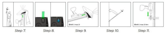
 Extend Existing Beacon:
 - Remove the product from the settlement beacon pole using an impact drill or manually.
- Hold the magnet against the connection signal area ( ) on the bottom of the device. The LED should turn BLUE within 60 seconds if everything is functioning correctly. If it turns RED, take another device.
- Mount the product on an extension pole while the pole is laid horizontally.
- Rise the extension pole vertically and align the holes with the base plate.
- Bolt the extension pole to the base plate. (M10 bolts, max 21 Nm)
 Remove and Store:
 - Remove the product from the settlement beacon pole using an impact drill or manually.
- Remove bird spikes from the device.
- Store the product preferably in its original cardboard box or another secure place.

Frequency Bands
The device works with LTE-M connectivity and has a radar inside.
LTE-M
This device operates in the following LTE-M frequency bands if available in a region:
- Band 1: 2100 MHz (Uplink: 1920 – 1980 MHz, Downlink: 2110 – 2170 MHz)
- Band 2: 1900 MHz (Uplink: 1850 – 1910 MHz, Downlink: 1930 – 1990 MHz)
- Band 3: 1800 MHz (Uplink: 1710 – 1785 MHz, Downlink: 1805 – 1880 MHz)
- Band 4: 1700/2100 MHz (Uplink: 1710 – 1755 MHz, Downlink: 2110 – 2155 MHz)
- Band 5: 850 MHz (Uplink: 824 – 849 MHz, Downlink: 869 – 894 MHz)
- Band 8: 900 MHz (Uplink: 880 – 915 MHz, Downlink: 925 – 960 MHz)
- Band 12: 700 MHz (Uplink: 699 – 716 MHz, Downlink: 729 – 746 MHz)
- Band 13: 700 MHz (Uplink: 777 – 787 MHz, Downlink: 746 – 756 MHz)
- Band 14: 700 MHz (Uplink: 788 – 798 MHz, Downlink: 758 – 768 MHz)
- Band 18: 800 MHz (Uplink: 815 – 830 MHz, Downlink: 860 – 875 MHz)
- Band 19: 800 MHz (Uplink: 830 – 845 MHz, Downlink: 875 – 890 MHz)
- Band 20: 800 MHz (Uplink: 832 – 862 MHz, Downlink: 791 – 821 MHz)
- Band 25: 1900 MHz (Uplink: 1850 – 1915 MHz, Downlink: 1930 – 1995 MHz)
- Band 26: 850 MHz (Uplink: 814 – 849 MHz, Downlink: 859 – 894 MHz)
- Band 28: 700 MHz (Uplink: 703 – 748 MHz, Downlink: 758 – 803 MHz)
- Band 66: 1700/2100 MHz (Uplink: 1710 – 1780 MHz, Downlink: 2110 – 2200 MHz)
Radar:
This radar operates (if it’s shut on by the applicant) in the following frequency band:
The band is listed as 57 – 64 GHz with a rated EIRP of 10dBm (maximum with the lenses) with measuring the output power over a 0.3ns time window.
Warnings and Compliance
FCC Part 15.19:
This device complies with Part 15 of the FCC Rules. Operation is subject to the following two conditions: (1) this device may not cause harmful interference, and (2) this device must accept any interference received, including interference that may cause undesired operation.
FCC Part 15.21:
Changes or modifications not expressly approved by the party responsible for compliance could void the user’s authority to operate the equipment.
FCC Part 20.21 (for amplifiers):
This device does not contain amplifiers and is not subject to the amplifier regulations of Part 20.21.
Charging
The device will be charged by the solar panel during daylight. Ensure the solar panel is exposed to sufficient sunlight for optimal performance.
Hardware Interfaces
The device has the following hardware interfaces:
Magnet Usage: The magnet is used to test the device’s functionality by holding it against the connection signal area ( ) at the bottom (see step 4. in the installation instructions). If the LED turns BLUE within 60 seconds, the device is operational and everything is functioning correctly. If RED, you need to replace the device.
12-pins Adapter: This adapter can be used by the manufacturer to configure sensors in the device.
Updates: All updates are performed via OTAU (Over-The-Air Updates) without using cables.
Maintenance and Troubleshooting
Solar Panel: Keep the solar panel clean and free from dust to ensure efficient charging.
GNSS-Signals: Ensure the device has a clear view of the sky for optimal GNSS signal reception.
Magnet Test: Use the magnet to check the device’s functionality as described in the hardware interfaces section.
Regulatory Statements
FCC Statements:
This device complies with all relevant FCC regulations and standards. For complete FCC statements and compliance information, refer to the attached documentation or visit our website.
UKCA Statements:
This device meets the requirements for UKCA marking as per UK regulations. The UKCA marking indicates conformity with the relevant UK statutory requirements.
For more detailed information on UKCA compliance, please refer to the accompanying documentation or visit our website.
CE Statements:
This device complies with the essential requirements and other relevant provisions of the EU directives. The CE marking indicates conformity with the relevant EU standards and directives. For more detailed information on CE compliance, please refer to the accompanying documentation or visit our website.
RED Statements:
This device complies with the relevant Radio Equipment Directive regulations and standards. For more detailed information on RED compliance, refer to the attached documentation or visit our website.
Standards applied:
- EN 305 550-2 V1.2.1 (2014)
- EN 305 550-1 V1.2.1 (2014)
- EN 301 908-1 V13.1.1 (2019)
- EN IEC 62368-1:2020 + A11:2020 (2020)
- EN 60529:1991 + A1:2000 + A2:2013 (2013)
- EN 301 908-1 V15.2.1 (2023)
- EN 301 908-13 V13.2.1 (2022)
- EN 62311 (2020)
- EN 301 489-1 V2.2.3 (2019)
- EN 301 489-3 V2.3.2 (2023)
- EN 301 489-52 V1.2.1 (2021)
Regulatory Information
Regulatory information USA
Information to the User (Part 15.105 (b))
Note: This equipment has been tested and found to comply with the limits for a Class A digital device, pursuant to part 15 of the FCC Rules. These limits are designed to provide reasonable protection against harmful interference in a residential installation. This equipment generates, uses and can radiate radio frequency energy and, if not installed and used in accordance with the instructions, may cause harmful interference to radio communications. However, there is no guarantee that interference will not occur in a particular installation. If this equipment does cause harmful interference to radio or television reception, which can be determined by turning the equipment off and on, the user is encouraged to try to correct the interference by one or more of the following measures:
- Reorient or relocate the receiving antenna.
- Increase the separation between the equipment and receiver.
- Connect the equipment into an outlet on a circuit different from that to which the receiver is connected.
- Consult the dealer or an experienced radio/TV technician for help.
To comply with FCC RF radiation exposure limits for general population, the antenna(s) used for this transmitter must be installed such that a minimum separation distance of 20 cm is maintained between the radiator (antenna) and all persons at all times and must not be co-located or operating in conjunction with any other antenna or transmitter.
Regulatory information Canada
This Class A digital apparatus complies with Canadian ICES-003.
To comply with Industry Canada RF radiation exposure limits for general population, the antenna(s) used for this transmitter must be installed such that a minimum separation distance of 20 cm is maintained between the radiator (antenna) and all persons at all times and must not be co-located or operating in conjunction with any other antenna or transmitter.
This device contains license-exempt transmitter(s)/receiver(s) that comply with Innovation, Science and Economic Development Canada’s license-exempt RSS(s).
Operation is subject to the following two conditions:
(1) This device may not cause interference;
(2) This device must accept any interference, including interference that may cause undesired operation of the device.![]()
Documents / Resources
 |
Basetime Locator One Geodetic Monitoring System [pdf] User Manual Locator One Geodetic Monitoring System, Geodetic Monitoring System, Monitoring System |