
Features

Banner’s TL70 Pro Ethernet Modular Tower Light is a 70 mm, modular LED indicator with bright and uniform light. The modularity gives the user flexibility to customize tower lights as needed and change positions in the field. The TL70 is also available preassembled for easy installation.
- Modbus TCP/IP, EtherNetIP, and PROFINET control allows access to full color, flashing, and dimming settings, as well as advanced animations and audible tones
- Up to five indicator segments and one audible segment in one device
- Rugged, water-resistant IP65 housing with UV-stabilized material
- Bright, uniform indicator segments appear gray when off to eliminate false indications from ambient light
- Simple and fast connection with M12 quick-disconnect connector
Models
Segment Models
| Model | Description |
| SG-TL70P-L | RGB light segment |
| SG-TL70P-A | Audible segment |
Base Models
| Model | Description |
|
B-TL70POE-QPD |
Power over Ethernet (PoE) base module with 475 mm (18.7 in) cable with a 4-pin D-Code M12 female quick-disconnect connector |
|
B-TL70PE-Q2PE |
Ethernet base module with dual cables:
• One 475 mm (18.7 in) cable with a 4-pin D-Code M12 female quick-disconnect connector • One 475 mm (18.7 in) cable with a 4-pin A-Code M12 male quick-disconnect connector |
Pre-Assembled Models
| Model | Description |
|
TL70POE3QPD |
Power over Ethernet (PoE) with three RGB segments |
|
TL70POE3AQPD |
Power over Ethernet (PoE) with three RGB segments and an audible segment |
| L70PE3Q2PE | Ethernet with three RGB segments |
|
TL70PE3AQ2PE |
Ethernet with three RGB segments and an audible
segment |
Installation Instructions
Assembling the Modules

To assemble the modules:
- Align the notches on each module and press together.
- Rotate the top module clockwise to lock into place (notches shown in the locked position).
Wiring
Wiring for Power over Ethernet (PoE) Models
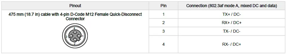
Wiring for Ethernet Models
| Pinout | Pin | Connection |
| 475 mm (18.7 in) cable with 4-pin D-Code M12 Female Quick-Disconnect Connector
|
1 | TX+ |
| 2 | RX+ | |
| 3 | TX- | |
|
4 |
RX- |
|
| 475 mm (18.7 in) cable with 4-pin A-Code M12 Male Quick-Disconnect Connector
|
1 | Brown wire: 18 V DC to 30 V DC |
| 2 | White wire: Unused | |
| 3 | Blue wire: DC common | |
|
4 |
Black wire: Unused |


Configuration Instructions
For more information about the TL70 Pro Ethernet Modular Tower Light device registers, refer to document PN 243473.
Modbus TCP and EtherNet/IP Configuration
- By default, the TL70 Pro Ethernet Tower Light is configured to communicate via Modbus TCP or EtherNet/IP without the need to connect the device to a computer for setup.
- Plug the tower light into a switch, and use the default IP address of 192.168.0.1 and subnet mask of 255.255.255.0 to connect via Modbus TCP or EtherNet/IP.
PROFINET Configuration
Connect the TL70 Ethernet Tower Light to the computer directly or through a switch.
- Open the DXM Configuration Software and select DXMR90x from the Select DXM Model drop-down menu.
- Click Scan Network for DXMs to find the correct IP Address, or enter the IP Address directly if it is known.
- Click Connect.

IMPORTANT: Import the tower light configuration before making any changes to the program. Select DXM › Get Configuration from DXM in the toolbar menu to save the configuration to the computer and import it into the software.
After the configuration is imported:
- Select Settings.
- Select Ethernet.
- Check Enable Profinet.

When complete, select File › Save, and then select DXM and Send Configuration to DXM to send the PROFINETenabled configuration to the tower light.
The tower light can now be connected over PROFINET.
Tower Light Segment Modes
Basic Segment Mode
- Use a single run time register per LED segment to set it to Off, On, Flash, or Animation mode.
- Use a single run time register for an audible segment to set it to Off or On.
- Use additional configuration registers to change color, intensity, flash speed, and select animation type on LED segments and change volume and tone on audible segment.
Advanced Segment Mode
- Use multiple run time registers per LED segment to control color, intensity, flash, and other animation types.
- Use multiple run time registers for an audible segment to control sync, volume, and tone settings.
- Use additional configuration registers to create custom intensity and flash speeds.
LED Segment Control
| Animation | Description |
| Off | Segment is off |
| Steady | Color 1 is solid on at defined intensity |
| Flash | Color 1 flashes at defined speed, color intensity, and pattern |
| Two Color Flash | Color 1 and Color 2 flash alternately at defined speed, color intensities, and pattern |
| 50/50 | Color 1 is displayed on 50% of the segment and Color 2 is displayed on the other 50% of the segment at the defined color intensities |
|
50/50 Rotate |
Color 1 is displayed on 50% of the segment and Color 2 is displayed on the other 50% of the segment while rotating at the defined speed and color intensities |
|
Chase |
Color 1 is displayed as a single spot against the background of Color 2 while rotating at the defined speed, color intensities, and rotational direction |
| Intensity Sweep | Color 1 repeatedly increases and decreases intensity between 0% to 100% at defined speed and color intensity |
| Demo | Demo sequence cycles through several sets of colors and configurations to highlight example applications |
Audible Segment Control
| Setting | Description |
| Audible State | Sets the segment to off, on, or synced to flash pattern of last LED segment |
| Audible Volume | Defines the volume of the audible tone |
| Audible Tone | Defines the audible tone frequency |
Specifications
Supply Voltage
- Power over Ethernet models: 42.5 V DC to 57 V DC
- PoE (Class 0 – 802.3af, 802.3at Type 1)
- Ethernet models: 18 V DC to 30 V DC
Supply Current
|
Device |
Typical Current (mA) per Device |
Max Current (mA) |
|||||
| 18 V DC | 24 V DC | 30 V DC | 42.5 V DC | 50 V DC | 57 V DC | ||
| PoE base | – | – | – | 40 | 35 | 30 | 50 |
| Ethernet base |
60 |
45 |
40 |
– |
– |
– |
75 |
| Light and Audible segment |
110 |
85 |
75 |
45 |
40 |
35 |
125 |
Environmental Rating
- IP65
Supply Protection Circuitry
- Protected against reverse polarity and transient voltages
Initial Startup Time
- 30 seconds
Construction
- Bases, segments, and covers: polycarbonate
Connections
- See
Operating Temperature
- –40 °C to +50 °C (–40 °F to +122 °F)
- 95% at +50 °C maximum relative humidity (non-condensing)
Audible Alarm
- Tone 0: 1.7 kHz ± 250 Hz oscillation frequency; maximum intensity (typical) 81 dB at 1 m (3.3 ft)
- Tone 1: 2.2 kHz ± 250 Hz oscillation frequency; maximum intensity (typical) 100 dB at 1 m (3.3 ft)
- Tone 2: 2.7 kHz ± 250 Hz oscillation frequency; maximum intensity (typical) 104 dB at 1 m (3.3 ft)
Vibration and Mechanical Shock
- Meets IEC 60068-2-6 requirements (Vibration: 10 Hz to 55 Hz, 0.5 mm amplitude, 5 minutes sweep, 30 minutes dwell)
- Meets IEC 60068-2-27 requirements (Shock: 15G 11 ms duration, half sine wave)
Certifications
 Banner Engineering BV
- Park Lane, Culliganlaan 2F bus 3 1831 Diegem, BELGIUM
 Turck Banner LTD Blenheim House
- Blenheim Court
- Wickford, Essex SS11 8YT GREAT BRITAIN
Default Light Segment Characteristics
|
Color |
Dominant Wavelength (nm) or Color Temperature (CCT) | Color Coordinates(1) | Lumen Output Per Segment (Typical at 25 °C) | |
| X | Y | |||
| Green | 532 | 0.181 | 0.735 | 34.8 |
| Red | 621 | 0.691 | 0.308 | 15.4 |
| Yellow | 578 | 0.473 | 0.474 | 21 |
| Blue | 467 | 0.137 | 0.056 | 27.6 |
| White | 5700K | 0.328 | 0.337 | 29.7 |
| Cyan | 492 | 0.150 | 0.334 | 20.9 |
| Magenta | – | 0.379 | 0.177 | 18.7 |
| Amber | 590 | 0.552 | 0.414 | 6.6 |
| Rose | – | 0.508 | 0.230 | 9.3 |
| Lime Green | 565 | 0.393 | 0.535 | 23.8 |
| Sky Blue | 485 | 0.146 | 0.241 | 14.1 |
| Orange | 600 | 0.611 | 0.370 | 24.1 |
| Violet | – | 0.212 | 0.091 | 19.6 |
| Spring Green | 509 | 0.157 | 0.553 | 12.7 |
Dimensions

| Model | Height (H) |
| 1 light module | 87.6 mm (3.45 in) |
| 1 light module, 1 audible module | 144.3 mm (5.68 in) |
| 2 light modules | 137.3 mm (5.41 in) |
| 2 light modules, 1 audible module | 194 mm (7.64 in) |
| 3 light modules | 187 mm (7.36 in) |
| 3 light modules, 1 audible module | 243.7 mm (9.59 in) |
| 4 light modules | 236.7 mm (9.32 in) |
| 4 light modules, 1 audible module | 293.4 mm (11.55 in) |
| 5 light modules | 286.4 mm (11.28 in) |
| 5 light modules, 1 audible module | 343.1 mm (13.51 in) |
FCC STATEMENT
FCC Part 15 Class A for Unintentional Radiators
This equipment has been tested and found to comply with the limits for a Class A digital device, pursuant to Part 15 of the FCC Rules. These limits are designed to provide reasonable protection against harmful interference when the equipment is operated in a commercial environment. This equipment generates, uses, and can radiate radio frequency energy and, if not installed and used in accordance with the instruction manual, may cause harmful interference to radio communications. Operation of this equipment in a residential area is likely to cause harmful interference in which case the user will be required to correct the interference at his own expense.
(Part 15.21)
- Any changes or modifications not expressly approved by the party responsible for compliance could void the user’s authority to operate this equipment.
Industry Canada ICES-003(A)
This device complies with CAN ICES-3 (A)/NMB-3(A). Operation is subject to the following two conditions:
- This device may not cause harmful interference
- This device must accept any interference received, including interference that may cause undesired operation.
Accessories
Cordsets


Mounting Brackets
All measurements are listed in millimeters, unless noted otherwise.
SMB30A

- Right-angle bracket with curved slot for versatile orientation
- Clearance for M6 (¼ in) hardware
- Mounting hole for 30 mm sensor
- 12-gauge stainless steel
Hole center spacing: A to B=40
Hole size: A=ø 6.3, B= 27.1 × 6.3, C=ø 30.5
SMB30MM

- 12-gauge stainless steel bracket with curved mounting slots for versatile orientation
- Clearance for M6 (¼ in) hardware
- Mounting hole for 30 mm sensor
Hole center spacing: A = 51, A to B = 25.4
Hole size: A = 42.6 × 7, B = ø 6.4, C = ø 30.1
SMBAMS30P

- Flat SMBAMS series bracket
- 30 mm hole for mounting sensors
- Articulation slots for 90°+ rotation
- 12-gauge 300 series stainless steel
Hole center spacing: A=26.0, A to B=13.0
Hole size: A=26.8 × 7.0, B=ø 6.5, C=ø 31.0
SSA-MBK-EEC1

- Single 30 mm hole
- 8 gauge steel, black finish (powder coat)
- Front surface for customer-applied labels
Hole size: A = ø 7 , B = ø 30
LMBE12RA35

- Direct mounting of stand-off pipe, with common bracket type
- Zinc-plated steel
- 1/2-14 NPSM nut
- Mounting distance from the wall to the center of the 1/2-14 NPSM nut is 35 mm
Hole center spacing: 20.0
LMBE12RA45

- Direct mounting of stand-off pipe, with common bracket type
- Zinc-plated steel
- 1/2-14 NPSM nut
- Mounting distance from the wall to the center of the 1/2-14 NPSM nut is 45 mm
Hole center spacing: 35.0
Elevated Mount System


Foldable Mounting Brackets

LMB Sealed Right Angle Bracket

Limited Warranty
Banner Engineering Corp Limited Warranty
Banner Engineering Corp. warrants its products to be free from defects in material and workmanship for one year following the date of shipment. Banner Engineering Corp. will repair or replace, free of charge, any product of its manufacture which, at the time it is returned to the factory, is found to have been defective during the warranty period. This warranty does not cover damage or liability for misuse, abuse, or the improper application or installation of the Banner product.
THIS LIMITED WARRANTY IS EXCLUSIVE AND IN LIEU OF ALL OTHER WARRANTIES WHETHER EXPRESS OR IMPLIED (INCLUDING, WITHOUT LIMITATION, ANY WARRANTY OF MERCHANTABILITY OR FITNESS FOR A PARTICULAR PURPOSE), AND WHETHER ARISING UNDER COURSE OF PERFORMANCE, COURSE OF DEALING OR TRADE USAGE.
This Warranty is exclusive and limited to repair or, at the discretion of Banner Engineering Corp., replacement. IN NO EVENT SHALL BANNER ENGINEERING CORP. BE LIABLE TO BUYER OR ANY OTHER PERSON OR ENTITY FOR ANY EXTRA COSTS, EXPENSES, LOSSES, LOSS OF PROFITS, OR ANY INCIDENTAL, CONSEQUENTIAL OR SPECIAL DAMAGES RESULTING FROM ANY PRODUCT DEFECT OR FROM THE USE OR INABILITY TO USE THE PRODUCT, WHETHER ARISING IN CONTRACT OR WARRANTY, STATUTE, TORT, STRICT LIABILITY, NEGLIGENCE, OR OTHERWISE.
Banner Engineering Corp. reserves the right to change, modify or improve the design of the product without assuming any obligations or liabilities relating to any product previously manufactured by Banner Engineering Corp. Any misuse, abuse, or improper application or installation of this product or use of the product for personal protection applications when the product is identified as not intended for such purposes will void the product warranty. Any modifications to this product without prior express approval by Banner Engineering Corp will void the product warranties. All specifications published in this document are subject to change; Banner reserves the right to modify product specifications or update documentation at any time. Specifications and product information in English supersede that which is provided in any other language. For the most recent version of any documentation, refer to: www.bannerengineering.com.
For patent information, see www.bannerengineering.com/patents.
FAQ
Frequently Asked Questions
- Q: Can I customize the TL70 Pro Ethernet Modular Tower Light?
- A: Yes, the modularity of the TL70 Pro Ethernet Modular Tower Light allows for customization of tower lights as needed.
Information
© 2024. All rights reserved.
www.bannerengineering.com
Documents / Resources
 |
BANNER TL70 Pro Ethernet Modular Tower Light [pdf] Instruction Manual TL70 Pro, TL70 Pro Ethernet Modular Tower Light, Ethernet Modular Tower Light, Modular Tower Light, Tower Light, Light |


