![]()
SENTINEL-SENSE ADB -5 12
Installation & Operation Manual-041527
COPYRIGHT ACKNOWLEDGEMENTS
The contents of this document are the property of Applied Wireless Identifications Group, Inc. (AWID) and are copyrighted. All rights reserved. Any reproduction, in whole or in part, is strictly prohibited. For additional copies of this document please contact:
AWID
18300 Sutter Blvd Morgan Hill, CA 95037
http://www.AWID.com
The information contained herein has been carefully checked and is believed to be accurate, no responsibility is assumed for inaccuracies. AWID reserves the right to make changes without prior notice. This document is not covered by any warranty either expressed or implied. Any comments, corrections or additions to the contents of this document should be directed to AWID at the above address.
Copyright 2021 AWID, Printed in USA. All other trademarks are the property of their respective owners.
FCC COMPLIANCE
This device complies with Part 15 of the FCC Rules. Operation is subject to the following two conditions: (1) This device may not cause harmful interference, and (2) this device must accept any interference received, including interference that may cause undesired operation.
This equipment has been tested and found to comply with the limits for a Class B digital device, pursuant to Part 15 of the FCC Rules. These limits are designed to provide reasonable protection against harmful interference in a residential installation. This equipment generates, uses, and can radiate radio frequency energy and, if not installed and used in accordance with the instructions, may cause harmful interference to radio communications. However, there is no guarantee that interference will not occur in a particular installation. If this equipment does cause harmful interference to radio or television reception, which can be determined by turning the equipment off and on, the user is encouraged to try to correct the interference by one of the following measures:
-Reorient or relocate the receiving antenna.
-Increase the separation between the equipment and receiver.
-Connect the equipment into an outlet on a circuit different from that to which the receiver is connected.
-Consult the dealer or an experienced radio/TV technician for help.
FCC Caution: Any changes or modifications not expressly approved by the party responsible for compliance could void the user’s authority to operate this equipment.
This transmitter must not be co-located or operating in conjunction with any other antenna or transmitter.
Radiation Exposure Statement:
This equipment complies with FCC radiation exposure limits set forth for an uncontrolled environment. This equipment should be installed and operated with a minimum distance of 23 cm between the radiator & your body.
This module is intended for OEM integrators only. Per FCC KDB 996369 D03 OEM Manual v01 guidance, the following conditions must be strictly followed when using this certified module:
KDB 996369 D03 OEM Manual v01 rule sections:
List of applicable FCC rules
This module has been tested for compliance to FCC Part 15
Summarize the specific operational use conditions
The module is tested for standalone mobile RF exposure use conditions. Any other usage conditions such as co-location with another transmitter (s) or being used in a portable condition will need a separate reassessment through a class II permissive change application or new certification.
Limited module procedures Not applicable.
Trace antenna designs Not applicable.
RF exposure considerations
This equipment complies with FCC mobile radiation exposure limits set forth for an uncontrolled environment. This equipment should be installed and operated with a minimum distance of 23 cm between the radiator & your body. If the module is installed in a portable host, a separate SAR evaluation is required to confirm compliance with relevant FCC portable RF exposure rules.
Antennas
The following antennas have been certified for use with this module; antennas of the same type with equal or lower gain may also be used with this module. The antenna must be installed such that 23 cm can be maintained between the antenna and users.
| Manufacturer/ Brand |
Model | Antenna Type |
Antenna connector |
Max Gain (dBi) | Impedance (0) |
| AWD | ANT-915CPS | Patch | TNC, RP | 6. | 50 |
| AWD | ANT-915-CP-R | Patch | SMA, RP | 6. | 50 |
| AWD | ANT-2012 | Patch | SMA, RP | 5. | 50 |
| AWD | ANT-915-CC-05 | Patch | TNC, RP | 5. | 50 |
Label and compliance information
The final end product must be labeled in a visible area with the following: “Contains FCC ID: OGSADB512”. The grantee’s FCC ID can be used only when all FCC compliance requirements are met.
Information on test modes and additional testing requirements
This transmitter is tested in a standalone mobile RF exposure condition and any co-located or simultaneous transmission with another transmitter (s) or portable use will require a separate class II permissive change re-evaluation or new certification.
Additional testing, Part 15 Subpart B disclaimer
This transmitter module is tested as a subsystem and its certification does not cover the FCC Part 15 Subpart B (unintentional radiator) rule requirement applicable to the final host. The final host will still need to be reassessed for compliance to this portion of rule requirements if applicable.
As long as all conditions above are met, further transmitter test will not be required. However, the OEM integrator is still responsible for testing their end-product for any additional compliance requirements required with this module installed.
IMPORTANT NOTE: In the event that these conditions cannot be met (for example certain laptop configurations or co-location with another transmitter), then the FCC authorization is no longer considered valid and the FCC ID cannot be used on the final product. In these circumstances, the OEM integrator will be responsible for re-evaluating the end product (including the transmitter) and obtaining a separate FCC authorization.
Manual Information to the End-User
The OEM integrator has to be aware not to provide information to the end-user regarding how to install or remove this RF module in the user’s manual of the end product which integrates this module. The end-user manual shall include all required regulatory information/warning as shown in this manual.
OEM/Host manufacturer responsibilities
OEM/Host manufacturers are ultimately responsible for the compliance of the Host and Module. The final product must be reassessed against all the essential requirements of the FCC rule such as FCC Part 15 Subpart B before it can be placed on the US market. This includes reassessing the transmitter module for compliance with the Radio and EMF essential requirements of the FCC rules. This module must not be incorporated into any other device or system without retesting for compliance as multi-radio and combined
INDUSTRY CANADA COMPLIANCE
This device complies with ISED’s license-exempt RSS. Operation is subject to the following two conditions: (1) This device may not cause harmful interference, and (2) this device must accept any interference received, including interference that may cause undesired operation.
Radiation Exposure Statement:
This equipment complies with ISED radiation exposure limits set forth for an uncontrolled environment. This equipment should be installed and operated with a minimum distance of 34 cm between the radiator & your body.
This device is intended only for OEM integrators under the following conditions: (For module device use)
- The antenna must be installed such that 34 cm is maintained between the antenna and users, and
- The transmitter module may not be co-located with any other transmitter or antenna.
DETACHABLE ANTENNA USAGE
This radio transmitter [IC: 6449A-ADB512] has been approved by Innovation, Science, and Economic Development Canada to operate with the antenna types listed below, with the maximum permissible gain indicated. Antenna types not included in this list that have a gain greater than the maximum gain indicated for any type listed are strictly prohibited from use with this device.
| Manufacturer/ Brand |
Model | Antenna Type |
Antenna connector |
Max Gain (dBi) | Impedance (0) |
| AWD | ANT-915CPS | Patch | TNC, RP | 6. | 50 |
| AWD | ANT-915-CP-R | Patch | SMA, RP | 6. | 50 |
| AWD | ANT-2012 | Patch | SMA, RP | 5. | 50 |
| AWD | ANT-915-CC-05 | Patch | TNC, RP | 5. | 50 |
End Product Labeling This transmitter module is authorized only for use in devices where the antenna may be installed such that 34 cm may be maintained between the antenna and users. The final end product must be labeled in a visible area with the following: “Contains IC: 6449A-ADB512”.
Manual Information to the End User The OEM integrator has to be aware not to provide information to the end-user regarding how to install or remove this RF module in the user’s manual of the end product which integrates this module. The end-user manual shall include all required regulatory information/warning as shown in this manual.
NOTE: READ AND USE THIS MANUAL.
NOTE: FAILURE TO FOLLOW THE INSTALLATION GUIDE MAY RESULT IN POOR PERFORMANCE OR EVEN CAUSE PERMANENT DAMAGE TO THE READER, THUS VOIDING THE PRODUCT WARRANTY.
REVISION HISTORY
| Version No | Revised By | Date | Sections Affected | Remarks |
| 0.1 | AWID Engineering | 6/2021 | – | Initial version |
| 0.2 | AWID Engineering | 7/2021 | p.5 | Editorial- IC Compliance statement |
| 0.3 | AWID Engineering | 7/2021 | p.2, p.5 | Updated- FCC, IC Compliance |
INTRODUCTION
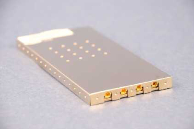
AWID’s Sentinel-Sense ADB-512 is a 4-port, long-range Radio Frequency Identification (RFID) reader module with 3.3 V TTL logical interface that works with most leading UHF passive tags. The reader module comes with a unique combination of long read range, small size, and low power consumption. Its primary applications are asset management and tracking, and fleet management applications.
ADB-512 is delivered with Firmware Version such as US0-60.xx.xx.
In order to operate an ADB-512, you will need the following:
- PC running Windows 7′ or higher, one serial port
- Host software (AWID’s demo software or your own custom software)
SPECIAL FEATURES
- Multi-Protocol: ISO-18000-6 Type C, EPC Class 1 Gen 2
- Thin passive tags with long-range performance
- 3.3 V (5.0V tolerable) Serial TTL logical interface
SPECIFICATION
| Input voltage Input current Idle Power Protocol language Read range RF connectors Output power Transmit frequency Receiver frequency Hopping channels Channel spacing Hopping sequence Operating temperature range Output data formats I/O Connector Dimension |
+5.8 VDC — 6 VDC (max) 1.4 A max @ +6VDC 0.5W in stand-by ISO Type C, EPC Class 1 Gen 2 Depends on type & size of labels used 4xMMCX (F) VSWR<1.2 @500HMs +30 dBm max 902.60-927.40 MHz 902.60-927.40 MHz (Amplitude Modulated) 125 Channels 200 kHz typical Pseudorandom -30° C to +65° C (-22° F to 149° F) (*) 3.3V TTL Serial 10-pin ZIF 2.11″x4.25″x0.35″ |
(*) depends on the heat sink size
CHANNEL FREQUENCY TABLE
Frequency range: 902.60 – 927.40 MHz
Minimum nun ber of frequency channels: 125
| CH | 902-928 | MHz | CH | 902-928 | MHz | CH | 902-928 | MHz | CH | 902-928 | MHz | CH | 902-928 | MHz |
| 0 | 902.60 | MHz | 25 | 907.60 | MHz | 50 | 912.60 | MHz | 75 | 917.60 | MHz | 100 | 922.60 | MHz |
| 1 | 902.80 | MHz | 26 | 907.80 | MHz | 51 | 912.80 | MHz | 76 | 917.80 | MHz | 101 | 922.80 | MHz |
| 2 | 903.00 | MHz | 27 | 908.00 | MHz | 52 | 913.00 | MHz | 77 | 918.00 | MHz | 102 | 923.00 | MHz |
| 3 | 903.20 | MHz | 28 | 908.20 | MHz | 53 | 913.20 | MHz | 78 | 918.20 | MHz | 103 | 923.20 | MHz |
| 4 | 903.40 | MHz | 29 | 908.40 | MHz | 54 | 913.40 | MHz | 79 | 918.40 | MHz | 104 | 923.40 | MHz |
| 5 | 903.60 | MHz | 30 | 908.60 | MHz | 55 | 913.60 | MHz | 80 | 918.60 | MHz | 105 | 923.60 | MHz |
| 6 | 903.80 | MHz | 31 | 908.80 | MHz | 56 | 913.80 | MHz | 81 | 918.80 | MHz | 106 | 923.80 | MHz |
| 7 | 904.00 | MHz | 32 | 909.00 | MHz | 57 | 914.00 | MHz | 82 | 919.00 | MHz | 107 | 924.00 | MHz |
| 8 | 904.20 | MHz | 33 | 909.20 | MHz | 58 | 914.20 | MHz | 83 | 919.20 | MHz | 108 | 924.20 | MHz |
| 9 | 904.40 | MHz | 34 | 909.40 | MHz | 59 | 914.40 | MHz | 84 | 919.40 | MHz | 109 | 924.40 | MHz |
| 10 | 904.60 | MHz | 35 | 909.60 | MHz | 60 | 914.60 | MHz | 85 | 919.60 | MHz | 110 | 924.60 | MHz |
| 11 | 904.80 | MHz | 36 | 909.80 | MHz | 61 | 914.80 | MHz | 86 | 919.80 | MHz | 111 | 924.80 | MHz |
| 12 | 905.00 | MHz | 37 | 910.00 | MHz | 62 | 915.00 | MHz | 87 | 920.00 | MHz | 112 | 925.00 | MHz |
| 13 | 905.20 | MHz | 38 | 910.20 | MHz | 63 | 915.20 | MHz | 88 | 920.20 | MHz | 113 | 925.20 | MHz |
| 14 | 905.40 | MHz | 39 | 910.40 | MHz | 64 | 915.40 | MHz | 89 | 920.40 | MHz | 114 | 925.40 | MHz |
| 15 | 905.60 | MHz | 40 | 910.60 | MHz | 65 | 915.60 | MHz | 90 | 920.60 | MHz | 115 | 925.60 | MHz |
| 16 | 905.80 | MHz | 41 | 910.80 | MHz | 66 | 915.80 | MHz | 91 | 920.80 | MHz | 116 | 925.80 | MHz |
| 17 | 906.00 | MHz | 42 | 911.00 | MHz | 67 | 916.00 | MHz | 92 | 921.00 | MHz | 117 | 926.00 | MHz |
| 18 | 906.20 | MHz | 43 | 911.20 | MHz | 68 | 916.20 | MHz | 93 | 921.20 | MHz | 118 | 926.20 | MHz |
| 19 | 906.40 | MHz | 44 | 911.40 | MHz | 69 | 916.40 | MHz | 94 | 921.40 | MHz | 119 | 926.40 | MHz |
| 20 | 906.60 | MHz | 45 | 911.60 | MHz | 70 | 916.60 | MHz | 95 | 921.60 | MHz | 120 | 926.60 | MHz |
| 21 | 906.80 | MHz | 46 | 911.80 | MHz | 71 | 916.80 | MHz | 96 | 921.80 | MHz | 121 | 926.80 | MHz |
| 22 | 907.00 | MHz | 47 | 912.00 | MHz | 72 | 917.00 | MHz | 97 | 922.00 | MHz | 122 | 927.00 | MHz |
| 23 | 907.20 | MHz | 48 | 912.20 | MHz | 73 | 917.20 | MHz | 98 | 922.20 | MHz | 123 | 927.20 | MHz |
| 24 | 907.40 | MHz | 49 | 912.40 | MHz | 74 | 917.40 | MHz | 99 | 922.40 | MHz | 124 | 927.40 | MHz |
Table 1 Channel Frequency Table for ADB-512
CONNECTOR PIN ASSIGNMENT
| Pin | Function | Pin | Function |
| 1 2 3 4 5 |
Reserved Reserved Reserved +6 VDC +6 VDC |
6 7 8 9 10 |
GND Unit Enable (*) SCIR SCIT GND |
(*) Note: pin 7 is internally pulled high. Users may leave this pin unconnected if manual control is not required
MEASURING READ DISTANCE
Make sure you know the tag types. For certain readers and tags, users must also be mindful of the tag’s orientation and the reader’s antenna orientation, what mounting surface the tags are designed for and how the tags are supposed to be mounted. Any departure from its intended purpose will drastically affect the reader’s ability to energize the tag and its read range.
When measuring the reader’s read range, make sure that the tag is properly oriented to the reader antenna, and for optimum performance, be sure the operator’s finger is not within three (3) inches of the tag’s antenna surface.
INSTALLATION & OPERATION GUIDELINES
For ease of explanation, the MPR reader in this section refers to an RFID device that consists of ADB-512 and a high-performance circular polarized antenna inside a splash-proof, UV stabilized housing case. The module should be installed on a heat sink. An example of a heat sink could be an aluminum plate of size 8″x8″x0.1″ exposed to convection airflow. The screws at the bottom of the module shall be used for mounting the module on the heat sink.
GENERAL WIRING REQUIREMENTS
ADB-512 requires a 10-pin flat flex cable (FFC) to connect from the supply source. Avoid using long (e.g., 10″ or longer) cables when connecting the unit from the power supply source.
INSTALLATION PROCEDURE
This section provides installation and operation information for ADB-512 reader modules.
PARTS LIST
Verify that all items listed below are present before starting the installation.
- Sentinel-Sense ADB-512 Qty=1
- Documentation Qty=1
PREPARATION FOR INSTALLATION
Familiarize yourself with the connectors and pin out the assignment of each I/O connector.
Bench Top Verification
It is always a good idea to verify system operation before committing to a full-scale installation. The following are the necessary steps to test the reader’s operation in a static environment.
- Connect ADB-512 to the RS-232 port of a PC through the interface board provided in the demonstration kit
- Connect the power jack from the wall plug power supply to the reader module
- Power up PC
- Install demo software on PC
- Activate demo software and verify the performance of the reader.
- Select COM port 1 on top page then click “Connect”. Follow with some commands.
SOFTWARE PROGRAMMING AND SYSTEM OPERATION NOTES
SYSTEM OPERATION
Running a Custom Software Application or the AWID Demo Program If AWID Demo Program is not used, it is expected user will launch a Custom Software Application developed using the MPR Communication Protocol and/or the supporting SDK (http://www.awid.com Support/Download) to issue commands to the MPR reader/module as specified.
USERS NOTE
For System Integrators and/or Software Developers
System Integrators and/or software developers should get familiar with the MPR Communication Protocol specifications and/or the supporting SDK for developing applications that control an ADB-512.
For Custom System Users
For custom system users, please refer to your host software user guide for information regarding system and software operations
For Demo Software Users
If you are using the AWID RFID demonstration software application which is .NET based with easy-to-follow GUI operations, simply select the COM port for which the ADB-512 is configured then click “Connect” should get you started.
Reference
MPR Communication Protocol Manual — Doc# 041479
MPR Command Demo II Quick Reference Guide — Doc# 041483
![]()
Documents / Resources
 |
AWiD ADB-512 UHF RFID Reader Module [pdf] Instruction Manual ADB512, OGSADB512, ADB-512 UHF RFID Reader Module, ADB-512, UHF RFID Reader Module |


