![]() Hardware Installation Manual
Hardware Installation Manual
AudioCodes MediaPack™ 5xx Analog Voice Gateway Series
MediaPack 516 (MP-516)
MediaPack 524 (MP-524)
MediaPack 532 (MP-532)
Notice
Information contained in this document is believed to be accurate and reliable at the time of printing. However, due to ongoing product improvements and revisions, AudioCodes cannot guarantee accuracy of printed material after the Date Published nor can it accept responsibility for errors or omissions. Updates to this document can be downloaded from https://www.audiocodes.com/library/technical-documents.
This document is subject to change without notice.
Date Published: September-15-2024
Security Vulnerabilities
All security vulnerabilities should be reported to vulnerability@audiocodes.com.
WEEE EU Directive
![]() Pursuant to the WEEE EU Directive, electronic and electrical waste must not be disposed of with unsorted waste. Please contact your local recycling authority for disposal of this product.
Pursuant to the WEEE EU Directive, electronic and electrical waste must not be disposed of with unsorted waste. Please contact your local recycling authority for disposal of this product.
Customer Support
Customer technical support and services are provided by AudioCodes or by an authorized AudioCodes Service Partner. For more information on how to buy technical support for AudioCodes products and for contact information, please visit our website at https://www.audiocodes.com/services-support/maintenance-and-support.
Stay in the Loop with AudioCodes

Abbreviations and Terminology
Each abbreviation, unless widely used, is spelled out in full when first used.
Throughout this manual, unless otherwise specified, the term device refers to the MediaPack 516 (MP-516), MediaPack 524 (MP-524), and MediaPack 532 (MP-532) analog voice gateway.
General Notes and Warnings
| The device must be installed only indoors. | |
| Warning: To power off the unit, disconnect both AC and DC power cords before service. | |
| The device must be installed only in a restricted access location that is compliant with ETS 300 253 guidelines where equipotential bonding has been implemented. | |
| Open-source software may have been added and/or amended. For further information, contact your AudioCodes sales representative. |
Safety Precautions
- Do not open or dismantle the device.
- Do not expose the device to water or moisture.
- Make sure the device is installed in a well-ventilated location to avoid overheating of internal components and subsequent damage.
- Make sure that sufficient clearance from the front and rear sides is maintained to ensure proper airflow to avoid overheating of internal components.
- Operate the device in an ambient temperature (Ta) that does not exceed 40°C (104°F).
![]() Warning: In case of a malfunction, do not attempt to fix the power adapter and do not use any other type of power adapter.
Warning: In case of a malfunction, do not attempt to fix the power adapter and do not use any other type of power adapter.
Related Documentation
Document Name
MediaPack 5xx User’s Manual Ver. 7.2
MSBR and MediaPack 5xx Series CLI Reference Guide Ver. 7.2
MSBR and MediaPack 5xx Series Release Notes Ver. 7.2
Document Revision Record
| LTRT | Description |
| 10615 | Initial document release. |
| 10616 | MP-516 added; FXS cabling using RJ-11 ports for MP-516 and MP-524 |
| 10617 | Note for grounding negative (-) of DC power supply |
| 10618 | Power label updated |
| 10619 | DC power wiring updated |
Documentation Feedback
AudioCodes continually strives to produce high quality documentation. If you have any comments (suggestions or errors) regarding this document, please fill out the Documentation Feedback form on our website at https://online.audiocodes.com/documentation-feedback.
Introduction
This document provides a hardware description of the device and step-by-step procedures for mounting and cabling the device.
The device provides the following interfaces:
- 2 x Gigabit Ethernet (10/100/1000Base-T) copper WAN port interfaces (RJ-45)
- 1 x Gigabit Ethernet (1000Base-T) LAN port interface (RJ-45)
- FXS telephony interfaces:
- MP-516 model: 16 x RJ-11 ports, providing 1-16 FXS port interfaces.
- MP-524 model:
- 1 x 50-pin D-Sub connector, providing 1-24 FXS port interfaces.
– Or – - 24 x RJ-11 ports, providing 1-24 FXS port interfaces.
- 1 x 50-pin D-Sub connector, providing 1-24 FXS port interfaces.
- MP-532 model: 2 x 50-pin D-Sub connectors, providing 1-24 and 25-32 FXS port interfaces, respectively.
- 1 x Serial console port (RJ-45) for device management
- 1 x USB Type-A for storage
Unpacking the Device
Follow the procedure below for unpacking the carton in which the device was shipped.
To unpack the device:
- Open the carton and carefully remove packing materials.
- Remove the chassis from the carton.
- Check that there is no equipment damage.
- Ensure that in addition to the chassis, the package contains the following items:
• Four anti-slide bumpers for desktop installation
• 2 x front-mounting brackets for 19-inch rack mounting
• Coupling nuts for 50-pin D-Sub connector(s):
♦ MP-532: x 4 (2 per connector)
♦ MP-524: x 2
• 1 x DC terminal block
• 1 x AC power cable
Physical Description
This section provides a physical description of the device.
3.1 Physical Dimensions and Operating Environment
The device’s physical dimensions and operating environment are listed in the table below:
Table 1: Physical Dimensions and Operating Environment
| Specification | Value |
| Dimensions (W x H x D) | 443 mm x 1U (44.45 mm) x 288 mm (17.44 x 1.75 x 11.34 in.) |
| Weight | 2.34 kg (5.16 lbs.) |
| Operating Environment | ◼Operational: 0 to 40°C (32 to 104°F) ◼ Storage: -40 to 70°C (-40 to 158°F) ◼ Relative Humidity: 5 to 95% non-condensing |
3.2 Front Panel Description
The front panel provides LEDs for indicating the status of various functionalities. The LEDs are shown in the figure below and described in the subsequent tables.

| 1 | – | Air openings |
| 2 | POWER / STATUS / AC / DC | LEDs indicating status of the following: ◼ Power (see POWER LED Description) ◼ Status (see STATUS LED Description) ◼ AC (see AC LED Description) ◼ DC (see DC LED Description) |
| 3 | 1-16 (MP-516) 1-24 (MP-524) 1-32 (MP-532) |
LEDs indicating the status of the FXS ports (see FXS LEDs Description). |
| 4 | CONSOLE | Console port (RJ-45) for RS-232 serial communication with the device. |
| 5 | USB 3.0 Type-A port interface for storage capabilities to a third-party, external USB storage device. | |
| 6 | // | Reset pinhole button. Use a paper clip or any other similar pointed object to press the button: ◼ Short press (less than 15 sec.): Resets the device. ◼ Pressing for more than 15 sec, but less than 30 sec: Restores the device to factory default. ◼ Pressing for longer than 30 sec: Device enters Rescue mode, where it attempts to download a new firmware file (.cmp). You should avoid this mode, unless done by qualified personnel. |
3.2.1 POWER LED Description
The POWER LED on the front panel indicates the device’s power status.
Table 2: POWER LED Description
| LED Color | LED State | Description |
| Green | On | Power received by device. |
| – | Off | No power. |
3.2.2 STATUS LED Description
The STATUS LED on the front panel indicates the operating status of the device.
Table 3: STATUS LED Description
| LED Color | LED State | Description |
| Green | On | Device is operational. |
| Flashing | ◼ Initial rebooting stage. ◼ Software upgrade (.cmp file) in process. |
|
| Red | On | Boot failure. |
| – | Off | Advanced rebooting stage or no power. |
3.2.3 AC LED Description
The AC LED on the front panel indicates the status of the AC power supply.
Table 4: AC LED Description
| LED Color | LED State | Description |
| Green | On | AC power is received by the device. |
| – | Off | No AC power received by the device. |
3.2.4 DC LED Description
The DC LED on the front panel indicates the status of the DC power supply.
Table 5: DC LED Description
| LED Color | LED State | Description |
| Green | On | DC power is received by the device. |
| – | Off | No DC power received by the device. |
3.2.5 FXS LEDs Description
The front panel provides LEDs for indicating the status of the FXS interfaces.
Table 6: LED Description of FXS Ports
| LED Color | LED State | Description |
| Green | On | Phone is in off-hook state. |
| Red | On | ◼ Port malfunction. ◼ Port disabled (using CLI command analog-port-enable) |
| – | Off | Phone is in on-hook state (or power not received by device). |
3.2.6 LAN LED Description
The LAN port on the front panel provides a LED for indicating the status of the LAN interface.
Table 7: LED Description of LAN Port
| LED Color | LED State | Description |
| Green | On | Ethernet link established. |
| Flashing | Data is being received or transmitted. | |
| – | Off | No Ethernet link. |
3.3 Rear Panel Description
The device’s rear panel is shown in the figure below and described in the subsequent table.

| 1 | Protective earthing (grounding) screw. | |
| 2 | 100-240V~1.5A 50-60Hz | AC power inlet. |
| 3 | 18-54V 7-3A | DC power input. |
| 4 | S2 / FXS | Port interface depends on MP-5xx model: ◼ MP-524/MP-532: 50-Pin D-Sub female connector for FXS ports 1-24. ◼ MP-516/MP-524: 16/24 RJ-11 ports for FXS ports 1-16/1-24, respectively. Note: MP-524 can be ordered with D-Sub connectors or RJ-11 ports. |
| 5 | S2 / FXS | 50-Pin D-Sub female connector for FXS ports 25-32. Note: This connector is available only on MP-532. |
| 6 | S0 / GE WAN | Two Gigabit Ethernet (GbE) ports (RJ-45) for WAN copper interfaces. |
| 7 | S1 / GE LAN | GbE (10/100/1000Base-T) port (RJ-45) for LAN interface. |
3.3.1 WAN LED Description
The WAN ports on the rear panel provide LEDs that indicate the status of the WAN interface.
Table 8: WAN Port LED Description
| LED Color | LED State | Description |
| Green | On | WAN GE link established. |
| Flashing | Data is being received or transmitted. | |
| – | Off | No WAN GE link or power not received by the device. |
Mounting the Device
You can mount the device using one of the following methods:
- Desktop/shelf mounting
- 19-inch Rack mounting
![]() The device must be installed only in a restricted access location that is compliant with ETS 300 253 guidelines where equipotential bonding has been implemented.
The device must be installed only in a restricted access location that is compliant with ETS 300 253 guidelines where equipotential bonding has been implemented.
4.1 Desktop / Shelf Mounting
Place the device on a desktop/shelf using the four anti-slide bumpers (supplied), which you need to stick on the grooves located on the underside of the device. The bumpers avoid involuntary movement of the unit on the desktop/shelf.
4.2 19-Inch Rack Mounting
You can mount the device in a standard 19-inch rack. This is done by using front-mounting brackets (supplied) and rear-mounting kit (not supplied). The length of the rear-mounting brackets can be adjusted to suit the distance between the device and the rear rack post.
- Front-mounting brackets (supplied):

- Rear-mounting kit / brackets (not supplied – orderable):

![]() Warning:
Warning:
- Elevated Operating Ambient: If installed in a closed or multi-unit rack assembly, consideration should be given to installing the equipment in an environment compatible with the maximum ambient temperature (Tmax) of 40°C (104°F).
- Reduced Air Flow: Installation should be such that the amount of air flow required for safe operation on the equipment is not compromised. Do not stack equipment one on top of the other and keep the ventilation openings on the front and rear panels free from cables or any objects to allow free air flow.
- Only one device can be mounted per rack mount shelf.
- The minimum vertical rack space for mounting the device in a 19-inch rack must be 2Us (3.5 in. or 88.9 mm).
![]() At least two people are required to mount the device in the 19-inch rack.
At least two people are required to mount the device in the 19-inch rack.
To mount device in 19-inch rack:
- Attach the left and right front-mounting brackets to the chassis, as shown below:

- Attach the two rear-mounting brackets to the two-rear rack posts, using two screws per bracket. Make sure that you attach the brackets at the same height level in the rack. See the figure below for correct orientation of the brackets when attaching them to the posts.

- Attach the rear-mounting flanges to the rear sides of the chassis, using the screws.

- With two people, lift the chassis into the rack from the front of the rack.
- Slide the two rear-mounting bracket flanges into the slide rails of the rear-mounting brackets that you previously attached to the rear posts.

- Hold the chassis in position while the second person secures the rear-mounting flanges to the rear-mounting brackets. Insert the screws from the inside of the rack, through the flange’s grid and into the screw hole on the rear-mounting bracket. Finger-tighten the screws but make sure that the screws are NOT fully tightened and that the flange can freely move on the slide rails of the rear-mounting bracket.

- Hold the chassis for support while the second person positions the chassis so that the frontmounting brackets are flush against the front-rack posts and that the holes of the frontmounting brackets align with the holes on the front-rack posts. Secure the two frontmounting brackets to the front posts, by finger-tightening 19-inch rack bolts (not supplied) to the rack posts.
- Tighten the bolts on the front-mounting brackets.
- With a Philips screwdriver, tighten the screws securing the rear-mounting flanges to the rearmounting brackets.
![]() ◼ Make sure that all the mounting brackets are attached at the same level to the mounting posts so that the chassis is supported in a horizontal position.
◼ Make sure that all the mounting brackets are attached at the same level to the mounting posts so that the chassis is supported in a horizontal position.
◼ If the depth of the rack exceeds the maximum length of the adjustable rear-mounting brackets, install an additional side rack post to accommodate the length of the RearMounting Bracket
Cabling the Device
This chapter describes device cabling.
5.1 Grounding and Surge Protection
![]() Protective Earthing
Protective Earthing
The equipment is classified as Class I EN 62368-1 and UL 62368-1 and must be earthed at all times.
Finland: Laite on liltettava suojamaadoituskoskettimilla varustettuun pistorasiaan.
Norway: Apparatet rna tilkoples jordet stikkontakt.
Sweden: Apparaten skall anslutas till jordat uttag.
![]() Grounding and Power Surge Protection
Grounding and Power Surge Protection
- The device must be installed only in telecommunication sites / centers in compliance with ETS 300-253 requirements “Earthing and Bonding of Telecommunication Equipment in Telecommunication Centers”.
- Prior to installation, earth loop impedance test must be performed by a certified electrician to ensure grounding suitability at the power outlet intended to feed the unit. It is essential that the impedance will be kept below 0.5 ohms!
- Proper grounding is crucial to ensure the effectiveness of the lightning protection, connect the device permanently to ground. The device’s grounding screw must be connected to the equipotential grounding bus bar located in the Telecommunication rack or installation site, using a wire of 6 mm2 surface wire. If the device is installed in a rack with other equipment, the rack must be connected to the equipotential grounding bus bar of the Telecommunication room, using a stranded cable with surface area of 25 mm2. The length of this cable must be as short as possible (no longer than 3 meters).
- As most of the installation is the responsibility of the customer, AudioCodes can assume responsibility for damage only if the customer can establish that the device does not comply with the standards specified above (and the device is within the hardware warranty period).
- The device complies with protection levels as required by EN 55035/EN 300386. Higher levels of surges may cause damage to the device.
To connect device to an earth ground:
- Prepare an adequate length (maximum 20 mm or 0.8 in.) of stranded grounding wire (16 AWG minimum size) for the ground connection, as shown in the following figure:

- Using a Philips-head screwdriver, remove the ground screw located on the rear panel, as shown below:

- Insert one end of the grounding wire into the grounding lug, and then use a crimping tool (not supplied) to secure the wire to the grounding lug.
- Attach the grounding lug to the chassis using the grounding screw.

- Connect the other end of the grounding wire to the building protective earth. This should be in accordance with the regulations enforced in the country in which the device is installed.
5.2 Connecting LAN Interface
The device provides a single Gigabit Ethernet (100/1000Base-T) port for connecting to the IP network (e.g., LAN).
Cabling specifications:
- Cable: Straight-through, Category (Cat) 5/5e/6 cable
- Connector: Standard RJ-45
- Connector Pinouts:
Table 9: RJ-45 Connector Pinouts for Ethernet Port
| Pin | Signal Name |
| 1 | Ethernet signal pair |
| 2 | |
| 3 | Ethernet signal pair |
| 6 | |
| 4 | Ethernet signal pair |
| 5 | |
| 7 | Ethernet signal pair |
| 8 | |
| Shield | Chassis ground |
To connect to LAN interface:
- Connect the RJ-45 connector at one end of the straight-through Ethernet cable to the Ethernet port labeled S1 / GE LAN, located on the rear panel:

- Connect the other end of the Ethernet cable to your LAN network.
5.3 Connecting WAN Interfaces
The device provides two copper Gigabit Ethernet (GbE) port interfaces (10/100/1000Base-T).
![]() Currently, only Port #1 can be used (Gigabit Ethernet 0/0). Port #2 will be enabled in a future software release (which will provide WAN active-standby redundancy).
Currently, only Port #1 can be used (Gigabit Ethernet 0/0). Port #2 will be enabled in a future software release (which will provide WAN active-standby redundancy).
Cable specification:
- Cable: straight-through Ethernet cable
- Connector: RJ-45
- Connector Pinouts:
Table 10: RJ-45 Connector Pinouts for Copper GbE WAN
| Pin | Signal Name |
| 1 | Ethernet signal pair |
| 2 | |
| 3 | Ethernet signal pair |
| 6 | |
| 4 | Ethernet signal pair |
| 5 | |
| 7 | Ethernet signal pair |
| 8 |
To connect device to WAN:
- Connect one end of a straight-through RJ-45 Ethernet cable to one of the RJ-45 ports labeled S0 / WAN GE, located on the rear panel.

- Connect the other end of the cable to the WAN network (e.g., ADSL or Cable modem).
5.4 Connecting FXS Analog Interfaces
Depending on MediaPack model, the device connects to FXS analog telephone equipment (e.g., fax machines, modems, or telephones) through the following FXS interfaces:
- MP-516: 16 x RJ-11 ports
- MP-524: 24 x RJ-11 ports or 1 x 50-Pin D-Sub female connector (depending on ordered hardware)
- MP-532: 2 x 50-Pin D-Sub female connectors for FXS ports 1-24 and 25-32, respectively.
5.4.1 Connecting FXS Interfaces using RJ-11 Ports
This section describes how to connect the device to FXS equipment using the RJ-11 ports.
![]() This section is applicable only to MP-516, and to MP-524 when ordered with RJ-11 ports.
This section is applicable only to MP-516, and to MP-524 when ordered with RJ-11 ports.
![]() FXS Outdoor Cabling and Power Surge Protection
FXS Outdoor Cabling and Power Surge Protection
- FXS port interface cabling must be routed only indoors and must not exit the building.
- Make sure that you connect the FXS ports to appropriate external devices; otherwise, damage to the device may occur.
- FXS ports are considered TNV-2.
Cable specifications:
- Cable: Straight-through RJ-11-to-RJ-11 telephone cable
- Connector Type: RJ-11
- Connector Pinouts:

To connect FXS interfaces:
- Connect one end of an RJ-11 cable (not supplied) to one of the FXS ports (labeled S2/FXS).
- Connect the other end of the cable to the telephone equipment (e.g., fax machine, dial-up modem, and analog POTS telephone).

5.4.2 Connecting FXS Interfaces using 50-Pin D-Sub Connector
This section describes how to connect the device’s 50-pin D-Sub connector(s) to FXS equipment.
![]()
- This section is applicable only to MP-524 (if ordered with the D-Sub connector) and MP-532.
- Make sure that you connect the FXS ports to appropriate external devices; otherwise, damage to the device may occur.
- FXS ports are considered TNV-2.
![]() FXS Outdoor Cabling and Power Surge Protection
FXS Outdoor Cabling and Power Surge Protection
- The device includes an integrated secondary surge protection, but not a primary telecom protection! When the FXS telephone lines are routed outside the building, additional protection, usually a 350V three-electrode Gas Discharge Tube (GDT) as described in ITU-T K.44, must be provided at the entry point of the telecom wires into the building (usually on the main distribution frame or MDF) in conjunction with proper grounding. The center pin of the GDT (MDF grounding bar) must be connected to the equipotential grounding bus bar of the Telecommunication room.
- Failure to install primary surge protectors and failure to comply with the grounding instructions or any other installation instructions may cause permanent damage to thedevice.
- The device complies with protection levels as required by EN 55035/ EN 300386. Higher levels of surges may cause damage to the device.
- To protect against electrical shock and fire, use a minimum of 26-AWG wire size to connect the FXS ports
FXS cabling specifications:
- Cable: You can use any of the following cables:
- AudioCodes orderable FXS Patch Panel (see Connecting FXS Interfaces using AudioCodes FXS Patch Panel on the next page)
- AudioCodes orderable 50-Pin D-Sub connector cable (10 m) to open leads, which needs to be connected to a distribution panel (see Connecting FXS Interfaces using Centronics Cable on page 28)
- Connector Type: 50-Pin D-Sub

- Connector Pinouts:
Table 11: 50-Pin D-Sub Connector Pinouts
| 50-Pin D-Sub Connector for FXS Ports 1-24 | 50-Pin D-Sub Connector for FXS Ports 25-32 | ||
| FXS Phone Channel (Ports) | Connector Pins | FXS Phone Channel (Ports) | Connector Pins |
| 1 | 1/26 | 25 | 1/26 |
| 2 | 2/27 | 26 | 2/27 |
| 3 | 3/28 | 27 | 3/28 |
| 4 | 4/29 | 28 | 4/29 |
| 5 | 5/30 | 29 | 5/30 |
| 6 | 6/31 | 30 | 6/31 |
| 7 | 7/32 | 31 | 7/32 |
| 8 | 8/33 | 32 | 8/33 |
| 9 | 9/34 | – | – |
| 10 | 10/35 | – | – |
| 11 | 11/36 | – | – |
| 12 | 12/37 | – | – |
| 13 | 13/38 | – | – |
| 14 | 14/39 | – | – |
| 15 | 15/40 | – | – |
| 16 | 16/41 | – | – |
| 17 | 17/42 | – | – |
| 18 | 18/43 | – | – |
| 19 | 19/44 | – | – |
| 20 | 20/45 | – | – |
| 21 | 21/46 | – | – |
| 22 | 22/47 | – | – |
| 23 | 23/48 | – | – |
| 24 | 24/49 | – | – |
| 25 (not used) | 25/50 | – | – |
5.4.2.1 Connecting FXS Interfaces using AudioCodes FXS Patch Panel
You can purchase AudioCodes’ 24-FXS ports patch panel to connect the FXS interfaces to your FXS equipment. The patch panel provides a 2-meter (78.7 in.) extension cable with a 50-Pin D-Sub male connector for connecting to the 50-Pin D-Sub connector on the device’s rear panel. All incoming wires from the 50-Pin D-Sub connector are terminated to the back of the patch panel. The FXS endpoints (e.g., telephones) can be plugged into the corresponding RJ-11 jacks on the front of the patch panel.
You can mount the patch panel in a 19-inch rack, using the integrated mounting brackets.

To connect FXS interfaces using AudioCodes FXS Patch Panel:
- Mount the Patch Panel in a 19-inch rack, using the integrated mounting brackets, located on either side of the Patch Panel. Use four 19-inch rack bolts (not supplied) to securely attach the brackets to the front-rack posts. Make sure that the left and right mounting brackets are attached to the rack posts at the same level so that the patch panel is supported in a horizontal position.

- Connect the Patch Panel’s 50-Pin D-Sub male connector to the device’s 50-Pin D-Sub female connector, located on the rear panel. Depending on the connector, secure it to the device’s connector using one of the following methods:
• Bail Locks:
a. Flip the two bail locks, located on either side of the connector, outwards.
b. Plug the male connector into the device’s female connector.
c. Flip the two bail locks inwards onto the male connector. • Coupling Nuts and Screws:
a. Using a Philips-head screwdriver, remove the two screws that are located on either side of the connector.
b. Screw the coupling nuts (supplied) into the holes from where you removed the screws.
c. Plug the male connector into the device’s female connector.
d. Secure the connector by screwing the male connector’s captive screws to the coupling nuts.
- Connect your analog equipment to the Patch Panel, by plugging the analog equipment’s RJ-11 connectors into the RJ-11 sockets on the Patch Panel’s front panel.
For outdoor FXS cabling installation, you MUST install additional power surge protection, as illustrated in the following figure. (For indoor FXS cabling installation, there is no need for primary lightning protection usage.)

5.4.2.2 Connecting FXS Interfaces using 50-Pin D-Sub to Open Leads Cable
You can use a cable with a 50-Pin D-Sub connector on one end and open leads on the other end (separately ordered from AudioCodes), as shown in the following figure, to connect the FXS interfaces to FXS equipment.
The cable is 10 meters in length (32.8 ft.) and provides a 50-Pin D-Sub male connector on one end and open leads on the other end. The open leads need to be connected to your patch panel or distribution frame.

To connect FXS interfaces using 50-Pin D-Sub to open leads cable:
- Connect the Patch Panel’s 50-Pin D-Sub male connector to the device’s 50-Pin D-Sub female connector, located on the rear panel. Depending on the connector, secure it to the device’s connector using one of the following methods:
• Bail Locks:
a. Flip the two bail locks, located on either side of the connector, outwards.
b. Plug the male connector into the device’s female connector.
c. Flip the two bail locks inwards onto the male connector. • Coupling Nuts and Screws:
a. Using a Philips-head screwdriver, remove the two screws that are located on either side of the connector.
b. Screw the coupling nuts (supplied) into the holes from where you removed the screws.
c. Plug the male connector into the device’s female connector.
d. Secure the connector by screwing the male connector’s captive screws to the coupling nuts.
- Terminate the wires on the other end of the cable to your patch panel or distribution frame.The wires are grouped in pairs with labels that indicate the FXS channels. Make sure that you connect the wires according to the correct channels as labelled on the wires.
- Connect your analog equipment to your patch panel or distribution frame, by plugging their RJ-11 connectors into the RJ-11 sockets on the patch panel or distribution frame.
5.5 Connecting a USB Device
The device supports USB storage capabilities using an external USB drive (stick) connected to the device’s USB 3.0 Type-A port.
USB storage capabilities include the following:
- Saving network captures to USB
- Upgrading software firmware from USB
- Updating configuration from USB
- Saving current configuration to USB
To connect a USB storage device:
- Connect your USB storage device to the USB port labeled
 , located on the front panel.

5.6 Connecting Serial Interface
The device provides an RS-232 serial interface port for accessing the device’s command line interface (CLI) for serial communication.
![]() The RS-232 serial port is not intended for permanent connection.
The RS-232 serial port is not intended for permanent connection.
Cable specifications:
- Port Type: RJ-45
- Cable: RJ-45 to DB-9 female cable adapter

 This cable is a separate orderable item from AudioCodes.
 - Connector Pinouts:
Table 12: RJ-45 to DB-9 Serial Cable Connector Pinouts
| RJ-45 | DB-9 Female | ||
| Pin | Signal | Pin | Signal |
| 1 | Internally used | 8 | Not used |
| 2 | Ground (GND) | 6 | Ground (GND) |
| 3 | Transmit Data (TXD) | 2 | Receive Data (RXD) |
| 4 | Internally used | 5 | Not used |
| 5 | Internally used | 5 | Not used |
| 6 | Receive Data (RXD) | 3 | Transmit Data (TXD) |
| 7 | Ground (GND) | 4 | Ground (GND) |
| 8 | Internally used | 7 | Not used |
To connect serial interface:
- Connect the RJ-45 connector, at one end of the cable adapter to the device’s serial port labeled CONSOLE, located on the front panel.

- Connect the DB-9 connector at the other end of the cable to the COM RS-232 communication port on your computer.
5.7 Connecting Power
The device can be powered from an AC or a DC power source.
For power redundancy, you can connect the device to both an AC and a DC power source. In this setup, the device gets its power from the AC power source. Only if there is an outage in the AC power source does the device use the DC power source for power.
![]()
![]() IEC 60417-6042 (2010-11)
IEC 60417-6042 (2010-11)
![]()
![]() IEC 60417-6172 (2012-09)
IEC 60417-6172 (2012-09)
![]() Warning: To power off the unit, disconnect both AC and DC power cords before service.
Warning: To power off the unit, disconnect both AC and DC power cords before service.
5.7.1 Connecting to AC Power
The device can be powered from a standard alternating current (AC) electrical outlet. The connection is made using the supplied AC power cord.
Table 5-13: AC Power Specifications
| Physical Specification | Value |
| Input Voltage | Single universal AC power supply 100-240V |
| AC Input Frequency | 50-60 Hz |
| Max. AC Input Current | 1.5 A |
![]() ◼ The device must be connected to a socket-outlet providing protective earthing connection.
◼ The device must be connected to a socket-outlet providing protective earthing connection.
◼ To avoid electric shock or fire, use only the AC power cord that is supplied by AudioCodes.
To connect device to AC power:
- Connect the line socket of the AC power cord (supplied) to the device’s AC power socket, located on the rear panel.

- Connect the plug at the other end of the AC power cord to a standard electrical outlet. The POWER and AC LEDs on the front panel should light up green.
5.7.2 Connecting to DC Power
You can power the device from a DC power source.
Table 14: DC Power Specification
| Physical Specification | Value |
| DC Input Ratings | +18 to +54 VDC; 7 to 3 A; Typical +48 VDC |
| Connection to DC Mains Supply | Terminal block (supplied) |
![]() DC Power Safety Notice:
DC Power Safety Notice:
- Do not connect the device to a regular Telecom -48V source.
- Connect the device to a safety extra-low voltage (SELV) source that is sufficiently isolated from the mains.
- Make sure that the negative (-) side of the power supply is grounded (earthed), as shown in Figure 29 below.
- The device must be permanently connected to earth (ground), as described in Grounding and Surge Protection.
- Connection of the device to the DC mains power must be done only by a certified electrician and in accordance with local national electrical regulations.

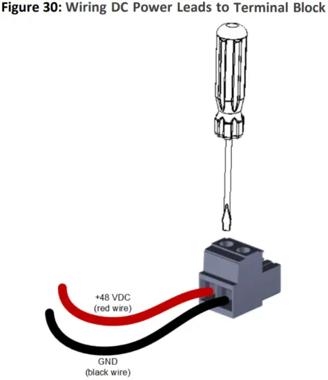
The device is shipped with a DC terminal block plug. You need to connect two 6-AWG power leads (one positive and one negative) to the terminal block.
To connect device to DC power:
- Disconnect your DC wires from your DC power source.
- Using a wire-stripping tool, strip the ends of the two wires (6-AWG) to a length that is sufficient for inserting into the supplied terminal block. Make sure that you do not strip too much of the insulation so that wire is not exposed when it exits the terminal block plug after it has been secured to the terminal block.
- Identify the polarity (negative and positive) of the two DC power feed wires. Polarity of power feed wires are typically color-coded, where red is positive (+48 VDC) and black is negative (GND).
- Insert the exposed wire of one of the two DC-input power source wires into the correct opening (according to polarity) on the terminal block plug (supplied), as shown in the figure. Make sure that only wire with insulation exits the terminal block. Using a Philips or flathead screwdriver, tighten the captive screw located above the installed wire lead to secure the wire to the terminal block. Repeat steps 1 through 5 for the second wire.
- Make sure that no wire strands are left outside the connector and that all strands have been clamped under the terminal block screw.
- Gently try and pull the wires from the terminal block. Only if the wires remain secured to the terminal block may you continue to the next step; otherwise, if the wires become free, repeat Step 5 to secure the wires to the terminal block.
- Insert the DC terminal block plug into the DC inlet located on the device’s rear panel.

- Connect the DC power leads to a +48 VDC power source.
International Headquarters
Naimi Park
6 Ofra Haza Street
Or Yehuda, 6032303, Israel
Tel: +972-3-976-4000
Fax: +972-3-976-4040
AudioCodes Inc.
80 Kingsbridge Rd
Piscataway, NJ 08854, USA
Tel: +1-732-469-0880
Fax: +1-732-469-2298
Contact us: https://www.audiocodes.com/corporate/offices-worldwide
Website: https://www.audiocodes.com
©2024 AudioCodes Ltd. All rights reserved. AudioCodes, AC, HD VoIP, HD VoIP Sounds Better, IPmedia, Mediant, MediaPack, What’s Inside Matters, OSN, SmartTAP, User Management Pack, VMAS, VoIPerfect, VoIPerfectHD, Your Gateway To VoIP, 3GX, VocaNom, AudioCodes One Voice, AudioCodes Meeting Insights, and AudioCodes Room Experience are trademarks or registered trademarks of AudioCodes Limited. All other products or trademarks are property of their respective owners. Product specifications are subject to change without notice.
Document #: LTRT-10619
![]()
Documents / Resources
 |
AudioCodes MP-516 Analog Voice Gateway [pdf] Installation Guide MP-516 Analog Voice Gateway, MP-516, Analog Voice Gateway, Voice Gateway, Gateway |