![]()
 System 20 PRO
2.4 GHz Wireless System
User Manual
Safety precautions
Important information
Warning
To prevent fire or shock hazard, do not expose this apparatus to rain or moisture.
Caution
- The rating label appears on the bottom of this apparatus.
- Do not place the product near fire to avoid an accident or the product catching fire.
- Keep the product out of the reach of small children. The product is not intended for use around children.
- Install this apparatus only in the place where ventilation is good.
- Do not install this apparatus in a confined space such as a bookcase or similar unit.
- To prevent fire, do not place any naked flame sources (such as lighted candles) on this apparatus.
- Do not place any objects filled with liquids, such as vases, on this apparatus.
- In case of emergency, disconnect the AC adapter quickly.
- This apparatus should be located close enough to the AC outlet so that you can easily grasp the AC adapter at any time.
- Do not subject this apparatus to strong impact.
- Do not expose this apparatus to excessive heat such as sunshine, fire or the like.
- Refer servicing to qualified personnel only.
- To avoid electric shock, do not open the cabinet.
- Do not expose this apparatus to drips or splashes.
Battery caution
| Product | Specified batteries/Rechargeable batteries |
| ATW-T1401/ATW-T1402 | Two alkaline AA Two lithium AA Two Ni-MH AA |
| ATW-T1406/ATW-T1407 | Dedicated lithium-ion battery |
- Keep batteries out of the reach of children.
- Observe correct polarity as marked.
- Do not expose the battery to excessive heat such as sunshine, fire or the like.
- Always consider the environmental issues and follow local regulations when disposing of batteries.
- Remove depleted battery immediately.
- Danger of explosion if battery is incorrectly replaced. Replace only with the same or equivalent type.
- Do not use a leaking battery. If battery leakage occurs, avoid contact with skin. If contact occurs, immediately wash thoroughly with soap and water.
- If battery leakage comes into contact with your eyes, immediately flush with water and seek medical attention.
- To protect the built-in rechargeable battery, charge it at least once every 6 months. If too much time passes between charges, the life of the rechargeable battery may be reduced, or the rechargeable battery may no longer be able to be charged.
Battery caution (ATW-T1401/ATW-T1402)
- Do not use different battery types or models.
- Do not use new and old batteries at the same time.
- Use only disposable LR6 (AA) alkaline or Ni-MH batteries or lithium batteries.
For customers in the USA
FCC Notice
Warning
This device complies with Part 15 of the FCC Rules. Operation is subject to the following two conditions: (1) This device may not cause harmful interference, and (2) this device must accept any interference received, including interference that may cause undesired operation.
Caution
You are cautioned that any changes or modifications not expressly approved in this manual could void your authority to operate this equipment.
Note
This equipment has been tested and found to comply with the limits for a Class B digital device, pursuant to part 15 of the FCC Rules. These limits are designed to provide reasonable protection against harmful interference in a residential installation. This equipment generates, uses and can radiate radio frequency energy and, if not installed and used in accordance with the instructions, may cause harmful interference to radio communications.
However, there is no guarantee that interference will not occur in a particular installation. If this equipment does cause harmful interference to radio or television reception, which can be determined by turning the equipment off and on, the user is encouraged to try to correct the interference by one or more of the following measures:
− Reorient or relocate the receiving antenna.
− Increase the separation between the equipment and receiver.
− Connect the equipment into an outlet on a circuit different from that to which the receiver is connected.
− Consult the dealer or an experienced radio/TV technician for help.
This transmitter must not be co-located or operated in conjunction with any other antenna or transmitter used in other systems.
RF Exposure Statement
(ATW-T1401/ATW-T1402)
This device complies with FCC radiation exposure limits set forth for an uncontrolled environment and meets the FCC radio frequency (RF) Exposure Guidelines. This equipment has very low levels of RF energy that is deemed to comply without testing of specific absorption rate (SAR).
(ATW-R1440/ATW-T1406/ATW-T1407)
This equipment should be installed and operated with a minimum distance of 20 cm between the radiator and your body.
Contact
Responsible Company: Audio-Technica U.S., Inc.
Address: 1221 Commerce Drive, Stow, Ohio 44224, USA
Tel: 330-686-2600
For customers in Canada
ISED statement
CAN ICES-003(B)/NMB-003(B)
This device contains licence-exempt transmitter(s)/receiver(s) that comply with Innovation, Science and Economic Development Canada’s licence-exempt RSS(s). Operation is subject to the following two conditions:
- This device may not cause interference.
- This device must accept any interference, including interference that may cause undesired operation of the device.
(ATW-R1440/ATW-T1406/ATW-T1407)
This equipment should be installed and operated with a minimum distance of 20 cm between the radiator and your body.
(ATW-T1401/ATW-T1402)
The available scientific evidence does not show that any health problems are associated with using low-power wireless devices. There is no proof, however, that these low-power wireless devices are absolutely safe. Low-power wireless devices emit low levels of radio frequency energy (RF) in the microwave range while being used. Whereas high levels of RF can produce health effects (by heating tissue), exposure of low-level RF that does not produce heating effects causes no known adverse health effects. Many studies of low-level RF exposures have not found any biological effects. Some studies have suggested that some biological effects might occur, but such findings have not been confirmed by additional research. ATW-T1401 and ATW-T1402 have been tested and found to comply with ISED radiation exposure limits set forth for an uncontrolled environment and meet RSS-102 of the ISED radio frequency (RF) exposure rules.
Notes on use
This system
- Be sure to read the user manual for any microphone or cable that you attach to the product.
- If you use the product near a TV or radio antenna, noise may be generated in the TV or radio. If this occurs, move the product away from the device.
- Be careful of interference noise caused by the surrounding radio wave environment and similar factors.
- This systemmay be affected by the spark noise of vehicles, dimmer of lighting apparatus, computers, office automation apparatus and electronic musical instruments. Place and use the product where it is less likely to be affected by the above.
- Be sure to use this system in combination with components specified by Audio-Technica.
- When installing this system, ensure that–wherever possible–there are no obstacles between the receiver unit and transmitter. If the antennas are hidden with this product rack-mounted, install the receiver unit externally.
- Over time, discoloration may occur due to ultraviolet rays (especially direct sunlight) and friction.
- It is legally prohibited to dismantle and modify this product. In addition, this product is so precisely manufactured that dismantling it could cause electric shock, failure, or fire. Never dismantle this product.
- When multiple units are used simultaneously, transmitters should be at least 1 m (3.3′) apart, and transmitters and receivers should be at least 2 m (6.6′) apart. Receivers that are not linked should be at least 1 m (3.3′) apart.
- When a howling, beeping or squealing sound is produced during use, turn down the output volume of the connected mixer/amplifier.
Receiver
- Be sure the connected cable is plugged all the way into the product.
Transmitter
- When used together with a guitar, the transmitter may easily be affected by magnetic noise depending on the type of pickup. If noise occurs, install the transmitter at least 30 cm (12″) away from the guitar pickup.
- If you use the transmitter close to an electronic or communications device (such as a mobile phone), the transmitter may produce unwanted noise. If this occurs, move the transmitter away from the device.
- To prevent depletion of the rechargeable batteries, turn off the transmitter when not in use and when not loaded in the charging station.
Maintenance
If the product becomes stained or covered with dust, wipe it off with a dry and soft cloth.
![]()
- Be sure to turn the device off before performing maintenance.
- Dirt easily adheres to the charging terminals of the transmitter and charging station. Charging may not be possible if these products are used with dirty terminals. If these terminals are dirty, wipe away this dirt with a cotton swab or something similar. Be careful not to apply too much force when doing so.
- Do not use benzene, thinner, or electrical contact cleaner, etc. Doing so may cause deformation, damage, or malfunction.
Devices compliant with this system
This system consists of the following devices.
Receiver 1. ATW-R1440
Quad Receiver
Transmitters (microphones)
- ATW-T1401
Body-Pack Transmitter - ATW-T1402
Handheld Transmitter - ATW-T1406
Boundary Microphone Transmitter - ATW-T1407
Desk Stand Transmitter
Charging station 1. ATW-CHG3a/ATW-CHG3Na
Two-Bay Charging Station
Part names and functions
ATW-R1440
This receiver is a combination of a receiver chassis (ATW-RC14) and receiver unit (ATW-RU14).
- Display
Displays the receiver state and settings menus. - Control dial
Turn the dial to select a setting item and press to confirm. - Power button
Turns the power on or off. - Receiver unit
You can remove this unit to install it externally. - BACK button
Press to take the display back one screen. Press and hold to return to the main screen. - CH MENU button
Press to display the channel settings menu. Each press of this button switches the channel to set. - NETWORK port
Connecting this port to a PC via Ethernet allows you to configure settings and monitor from the PC. - External receiver unit port
When externally installing the receiver unit, connect a LAN cable (Cat. 5e or higher) to this port. - AF balanced output connector (XLR 3-pin male)
- LINK IN port
When linking multiple receivers, connect the included link cable to this port. - LINK OUT port
When linking multiple receivers, connect the included link cable to this port. - DC input jack
Connect the included AC adapter.
ATW-RU14
- Antenna connector
Attach an included antenna. - Camera thread (1/4-inch)
Use this thread to secure the receiver unit when installing it externally. - Indicator lamp
Lights when the device is on. This lamp also shows the status of this receiver unit. Refer to “Indicator lamps” (p. 73) for details. - Latch module
This fixing module is used when the receiver unit is stored in the receiver chassis. - Internal connection terminal
- External connection port
When externally installing the receiver unit, connect the LAN cable (Cat. 5e or higher) from the receiver chassis to this port.
ATW-T1401
- Antenna
- Mute switch
Switches between muted and unmuted. - Input connector
Connect a microphone, a guitar cable, etc. - Indicator lamp
Lights when the device is on. This lamp also shows the status of this transmitter. Refer to “Indicator lamps” (p. 73) for details. - Latch
- Display
Shows the current status.
If no buttons are pressed for a period of 30 seconds, the display will turn off. When the display turns off, press the power button to turn it back on. - Power button
Turns the device on/off and performs pairing. - Belt clip
- Charging terminal
- USB port (USB Type-C™)
Use this port when updating the firmware. - Battery cover
ATW-T1402
- Display
Shows the current status.
If no buttons are pressed for a period of 30 seconds, the display will turn off. When the display turns off, press the power button to turn it back on. - Indicator lamp
Lights when the device is on. This lamp also shows the status of this transmitter. Refer to “Indicator lamps” (p. 73) for details. - Mute switch
Switches between muted and unmuted. - Grip case
- Power button
Turns the device on/off and performs pairing. - Charging terminal
- USB port (USB Type-C)
Use this port when updating the firmware.
ATW-T1406
- USB port (USB Type-C)
Use this port when charging the device and when updating the firmware. - Status indicator lamp
Lights when the device is on. This lamp also shows the status of this transmitter. Refer to “Indicator lamps” (p. 73) for details. - Microphone
- Talk switch
Switches between muted and unmuted. - Talk indicator lamp
Shows the muted/unmuted status. Refer to “Indicator lamps” (p. 73) for details. - Display
Shows the current status.
If no buttons are pressed for a period of 30 seconds, the display will turn off. When the display turns off, press the power button to turn it back on. - Power button
Turns the device on/off and performs pairing.
ATW-T1407
- USB port (USB Type-C)
Use this port when charging the device and when updating the firmware. - Status indicator lamp
Lights when the device is on. This lamp also shows the status of this transmitter. Refer to “Indicator lamps” (p. 73) for details. - Input connector
Use to connect a gooseneck microphone. - Talk switch
Switches between muted and unmuted. - Talk indicator lamp
Shows the muted/unmuted status. Refer to “Indicator lamps” (p. 73) for details. - Display
Shows the current status.
If no buttons are pressed for a period of 30 seconds, the display will turn off. When the display turns off, press the power button to turn it back on. - Power button
Turns the device on/off and performs pairing.
How to install the receiver
Low RF signal may result if there are obstructions between the receiver antennas and transmitter. In such a case,
reposition the receiver to get better reception.
How to mount the antennas
Failing to mount the included antennas on the receiver will result in poor radio wave reception.
- Mount the antennas on the receiver and screw them in.
Firmly tighten the antennas as far as they will go.
- Raise the antennas.
As a guideline, raise the antennas until they click.
As a further guideline, raise the two antennas in the center until the first time they click and the left and right antennas until the second time they click.
- Tilt the antennas to the left or right.
Tilt them 30 degrees to the left or right as shown in the figure.
Rack-mounting
Use the included rack-mount adapters and fixing screws to mount the receiver on a commercially available rack.
- Screws for rack-mounting the receiver are not included.
- The required rack specifications are as follows:
– EIA-standard 19-inch rack
– 1U-size attachable rack
– Rack with a shelf on which the receiver is placed or a guide rail that supports the receiver

![]()
- Consider ventilation when rack-mounting to avoid heat building up in the rack.
- When installing the product on a rack, make sure that the temperature inside the rack does not reach or exceed 45°C (113°F). Higher temperatures may negatively affect the internal parts of the product, causing the product to malfunction.
- Do not place any objects around the rear of this product to ensure proper ventilation.
Rack-mounting vertically stacked receivers
Make sure that the antennas of vertically stacked receivers do not touch. If they are touching, adjust their angles.
Rack-mounting one receiver
- Attach the short rack-mount adapter and long rack-mount adapter to the sides.
Adapters can be attached to either side of the receiver.
Fully attach two fixing screws to the left side and two fixing screws to the right side.
- Fixing screw
- Short rack-mount adapter
- Long rack-mount adapter
Rack-mounting two receivers
- Link the receivers by attaching two long rack-mount adapters to the bottom of the receivers.
Fully attach three fixing screws to both the left and right receivers. 1 Fixing screw
2 Long rack-mount adapter - Attach two short rack-mount adapters with one on each side.
Fully attach two fixing screws to the left side and two fixing screws to the right side. 1 Fixing screw
2 Short rack-mount adapter
How to mount the legs
For installation on a table or a similar surface, attach the included legs to the receiver.
- When rack-mounting the receiver, do not attach the legs to the receiver.

How to externally install the receiver unit
You can remove the receiver unit from the receiver chassis and install the receiver unit by itself.
How to remove the receiver unit
- Push the part labeled “PUSH”, and then remove the receiver unit.

How to install the receiver unit with the unit holder
- Straighten the antennas.
- Wood screws for attaching the unit holder to a wall or similar surface are not included.
Fixing the unit holder in place
- 1 Use wood screws to attach the unit holder to a wall.

Allowing the unit holder to be attached and removed
- Hang the unit holder on a wood screw partially screwed into a wall or similar surface.
The unit holder can be attached with either side facing up.
How to attach the receiver unit
- Use a LAN cable (Cat. 5e or higher) to connect the external receiver unit port of the receiver chassis and the external port of the receiver unit.

- Attach the receiver unit to the unit holder.

- If passing the LAN cable through the wall, attach the holder cover.
You can hide the LAN cable and the wiring hole.
How to remove the holder cover
While pressing the part indicated with the arrow, remove the cover. How to remove the receiver unit
- While pressing the hook, press the receiver unit from below to remove it.

How to link unit holders
You can link receiver units by aligning their grooves and protrusions. How to install the receiver unit with the camera thread
When using the angle of the camera thread, attach an angle to the camera thread (1/4-inch) of the receiver unit.
Basic flowof using this system
This section explains basic operations to allow for prompt use of this system. For detailed operations and setup methods, refer to their explanation pages.
- Install and wire the receiver and other devices.
- Pair the transmitter and the receiver.
If you purchased the transmitter and receiver as a set, they are already paired. - Input audio to the transmitter.
- Check that the audio is output from the connected speaker or similar device.
System configuration examples
ATW-R1440 (when using only one unit)
The maximum number of transmitters that can be used is two when the receiver reception mode is set to “Standard” and four when this mode is set to “HDmode”. ATW-R1440 (when using multiple units)
- The maximum number of receivers that can be used is five.
- When you are using five receivers, the maximum number of transmitters that can be used is 10 when the receiver reception mode is set to “Standard” and 20 when this mode is set to “HDmode”.

How to connect the receiver
Basic connection
This is an example of connections made when using one receiver.
- LAN cable
- XLR cable
- AC adapter
Linking (RX linking)
When using multiple receivers, link (RX link) themwith the included link cable.
- RX linking the receivers allows you to set and monitor all the connected receivers and transmitters from a single PC on whichWireless Manager is installed.
- The reliability of communication increases, and it is more difficult for sound dropouts to occur.
- There is less radio wave interference with other devices that use the 2.4 GHz frequency band.
- Up to five receivers can be connected.
- When receivers are RX linked, the reception mode of the expansion unit is changed to the setting on the base unit.
- Changing this setting deletes the pairing information.
- To use multiple receivers without RX linking them, position the receivers at a distance of at least 1 m (3.3′) from each other.
- Turn off all the receivers to connect.
- Use a link cable to connect the LINK OUT port of the receiver that is the base unit to the LINK IN port of the expansion unit.
- Use link cables to connect the LINK OUT ports to the LINK IN ports of the second and later pairs of units.
Amark appears in the link status part of the display when the connection is established.

- Base unit
- LAN cable
- XLR cable
- Link cable
- AC adapter
- Expansion unit
How to charge
Charging the ATW-T1401/ATW-T1402
Use charging station ATW-CHG3a/ATW-CHG3Na (sold separately) to charge the devices.
- For a detailed description of the charging station, see its user manual.
- Insert the nickel-metal hydride batteries into the transmitter before charging it.
- Do not charge alkaline batteries or lithium batteries.
- You can also charge with the ATW-CHG3/ATW-CHG3N.
1 Connect the AC adapter to the charging station, and then turn it on.
2 Insert the transmitters to charge into the charging ports of the charging station.
- You can charge up to two transmitters at the same time in one charging station.
- Check the orientation of the transmitters before inserting them. Transmitters cannot be charged if their orientation is not correct.
- When the charging of a transmitter starts, the status indicator lamp on the charging station lights in red.

![]()
- During charging, the transmitters turn off.
- If you insert a transmitter that is on into the charging station and remove it before 60 minutes have elapsed, the transmitter will automatically turn on again.
- If you insert a transmitter that is on into the charging station and remove it after at least 60 minutes have elapsed, the transmitter will remain off.
- Repeatedly charging a rechargeable battery will reduce its capacity. If the usage time of a battery becomes shorter, replace it with a new battery as soon as possible.
Charging the ATW-T1406/ATW-T1407
1. Connect the included USB cable / USB power supply adapter to the USB port (USB Type-C) of the transmitter.
- Insert the USB cable into the USB port in a straight (level) manner.
- When the charging starts, the status indicator lamp lights in red.
- You can also charge the device by connecting it to a USB port on a PC.
 1 USB cable
2 USB power supply adapter
![]()
The internal rechargeable battery in these products cannot be removed. The battery may have reached the end of its service life if the usage time becomes significantly shorter even after the battery has been fully charged. In this situation, contact your local Audio-Technica dealer.
How to use the devices
ATW-R1440
Turning the device on/off
- Connect the AC adapter, and then connect the power plug to an electrical outlet.
- With the device off, press and hold (approximately 2 seconds) the power button
 The device turns on and its display lights.
 - With the device on, press and hold (approximately 2 seconds) the power button.
The device turns off.
![]()
- It may take some time (approximately 30 seconds) for operations to become possible after the device turns on.
- If the supply of power from the electrical outlet is interrupted with the device on, it will automatically turn back on when the supply of power starts again.
ATW-T1401
How to insert batteries
- Slide the battery cover latches down.

- Open the battery cover while holding the latches down.

- Insert the batteries according to the plus (+) and minus (−) marks found inside the battery compartment.

Turning the device on/off
- With the device off, press and hold (approximately 2 seconds) the power button.
 The device turns on and its indicator lamp lights.
Indicator lamp Status Lit in green Communication has been established. Flashing in red The device is searching for the receiver to communicate with. - With the device on, press and hold (approximately 2 seconds) the power button.
The device turns off.
Switching between muted and unmuted
To change the setting, see “Setting the mute mode (ATW-T1401/ATW-T1402)” (p. 65) under “Channel settings”.
- Slide the mute switch.
Slide the mute switch right to mute the device and slide the mute switch left to unmute the device.
The indicator lamp displays the status. 1 Mute switch
2 Indicator lamp
| Indicator lamp | Status |
| Lit in red | Muted |
| Lit in green | Unmuted |
How to connect an external device
Connect an external microphone, guitar cable, or other device that supports the cW connector.
- Connect a microphone, etc. to the input connector.

![]()
- For details on handling the external device, see its user manual.
- For details on compatible external microphones, contact your local Audio-Technica dealer
How to wear the device
You can use the belt clip to attach the device to a belt or something similar when using the device. ATW-T1402
How to insert batteries
- Rotate the grip case of the battery compartment to remove this case.

- Open the battery cover.

- Insert the batteries according to the plus (+) and minus (−) marks found inside the battery compartment.

Turning the device on/off
- With the device off, press and hold (approximately 2 seconds) the power button.
 1 Power button
2 Indicator lamp
The device turns on and its indicator lamp lights.Indicator lamp Status Lit in green Communication has been established. Flashing in red The device is searching for the receiver to communicate with. - With the device on, press and hold (approximately 2 seconds) the power button.
The device turns off.
Switching between muted and unmuted
To change the setting, see “Setting the mute mode (ATW-T1401/ATW-T1402)” (p. 65) under “Channel settings”.
1 Slide the mute switch.
- Slide the mute switch down to mute the device and slide the mute switch up to unmute the device.
- The indicator lamp displays the status.

| Indicator lamp | Status |
| Lit in red | Muted |
| Lit in green | Unmuted |
ATW-T1406/ATW-T1407
Turning the device on/off
To change the setting, see “Setting the indicator lamp (ATW-T1406/ATW-T1407)” (p. 67) under “Channel settings”.
- With the device off, press and hold (approximately 2 seconds) the power button.
 The device turns on and its indicator lamp lights.
Indicator lamp Status Lit in green Communication has been established. Flashing in red The device is searching for the receiver to communicate with. Lit in red Communication has been established (in Conference mode). - With the device on, press and hold (approximately 2 seconds) the power button.
The device turns off.
Switching between muted and unmuted
- To change the setting, see “Setting the mute mode (ATW-T1406/ATW-T1407)” (p. 66) under “Channel settings”.
- To change the setting, see “Setting the indicator lamp (ATW-T1406/ATW-T1407)” (p. 67) under “Channel settings”.
1 Press the talk switch.
- For details on how to switch between muted and unmuted, see the set mute mode.
- The talk indicator lamp and status indicator lamp display the status.

| Talk indicator lamp / status indicator lamp | Status |
| Lit in red | Muted |
| Lit in green | Unmuted |
| Off | Muted (in Conference mode) |
| Lit in red | Unmuted (in Conference mode) |
How to attach a gooseneck microphone (ATW-T1407 only)
To use a gooseneck microphone, attach it to a desk stand transmitter.
1. Insert the gooseneck microphone into the desk stand transmitter.
- Turn off the transmitter before inserting the microphone.
- Insert the microphone until it clicks.

![]()
- Refer to the user manual of the gooseneck microphone for details on how to handle it.
- For details on compatible gooseneck microphones, contact your local Audio-Technica dealer.
When using a gooseneck microphone with an LED (ATW-T1407 only)
When using a gooseneck microphone with an LED, carry out the procedure under “Setting the indicator lamp (ATW- T1406/ATW-T1407)” (p. 67).
- LED
- Gooseneck microphone with an LED
How to remove a gooseneck microphone (ATW-T1407 only)
1 While pushing the part labeled “PUSH” on the desk stand transmitter, remove the microphone.
- Turn off the transmitter before removing the gooseneck microphone.

How to pair devices
In this user manual, making a receiver and transmitter register each other is referred to as a “pairing”.
- Set the receiver to pairing mode.
Refer to “Pairing mode” (p. 62) for details.
“Pairing” appears on the display of the receiver. - With the transmitter off, press and hold (approximately 5 seconds) the power button.
- When the indicator lamp of the transmitter flashes alternately between green and red, release this button.
“Pairing” appears on the display of the transmitter. - When pairing is complete, a completion screen appears on the display of the receiver.
The indicator lamp on the transmitter stops flashing and remains lit.
![]()
If the transmitter firmware is old, a message prompting you to update it will appear on the receiver. If this message appears, refer to “How to update the firmware” (p. 75) and update the firmware.
How to read the display
ATW-R1440
Main screen
- Name
Displays the set name. - Device ID
Displays the device ID of the receiver. - HD mode
Displayed during HDmode. - Mix output
Displayed during mix output. - Link status
Displayed during RX linking.
 : Displayed on the base unit.
 : Displayed on the expansion unit.
 - Network status
Displayed when the device is connected to a network. - Locked status
Displayed when the device is locked. - Channel
- Transmitter ID
- RF status
Displays the status of communication with the connected transmitter. - AF status
Displays the audio status of the connected transmitter.
 : Displayed when the level meter display is set to “Pre”. Displays the level of the received audio signal.
 : Displayed when the level meter display is set to “Post”. Displays the output level of the receiver.
 : Indicates that the device is at peak AF status.
 : Indicates that the device is muted.
 - Gain level
- Battery level
Displays the battery level of the connected transmitter.
 : Charging is in progress.
 : 70% or more battery power remaining.
 : 40% or more battery power remaining.
 : 20% or more battery power remaining.
 : 10% or more battery power remaining.
(flashing): 5% or less battery power remaining. Carry out battery replacement.
Receiver settings screen
Press the control dial on the main screen to display the receiver settings screen. Channel settings screen
Press the CHMENU button while on the main screen to display the channel settings menu.
- Each press of the CHMENU button switches the channel to set.
- You can set up to two channels when the reception mode is “Standard” and up to four channels when the reception mode is “HDmode”.

- Channel
- LINE/MIC status
- Output level
- Menu bar
- Transmitter ID
- AF status
- HPF status
 : The HPF is on.
 : The HPF is off.
ATW-T1401/ATW-T1402/ATW-T1406/ATW-T1407
Shows the current status.
- If no buttons are pressed for a period of 30 seconds, the display will turn off.
- When the display turns off, press the power button to turn it back on.

- Transmitter ID
- Gain level
- Battery level
Displays the battery level of the transmitter.
![]() : Charging is in progress.
: Charging is in progress.
![]() : 70% or more battery power remaining.
: 70% or more battery power remaining.
![]() : 40% or more battery power remaining.
: 40% or more battery power remaining.
![]() : 20% or more battery power remaining.
: 20% or more battery power remaining.
![]() : 10% or more battery power remaining.
: 10% or more battery power remaining.
![]() (flashing): 5% or less battery power remaining. Carry out battery charging or replacement.
(flashing): 5% or less battery power remaining. Carry out battery charging or replacement.
Displayed messages (ATW-R1440)
| Message | Description |
| No receiver unit | No receiver unit is connected to the receiver. |
| Initializing | The receiver unit is connecting to the receiver. |
| Exceeding Rx link limit | The number of sequential receivers that can be linked has been exceeded. Up to five receivers can be linked. |
| Rebooting | The receiver is restarting. |
| RU14 firmware is not matched Update it now? | The firmware of the connected receiver unit does not match that of the receiver. Select “Yes” to start the update. |
| A firmware update is available for Tx in A1. Pls update with Wireless Manager App via USB.[1][2] | There is old firmware on the transmitter being communicated with.
Use the dedicated software (Wireless Manager) to update. |
| Firmware updating… | The firmware of the receiver is being updated. |
[2] Use button operations to return to the main screen.
Setting ATW-R1440
Various settings can be made from the screens shown on the display.
Receiver settings
Basic operation
- Press the control dial.
 The receiver settings menu appears.
 - Turn the control dial to select the receiver settings menu and setting.
- Press the control dial to confirm the selection.
- Press the BACK button to go back one screen.
If a setting is being configured, it will be canceled.
Press and hold (approximately 2 seconds) to return to the main screen.
![]() While on the settings screen, the display will return to the main screen if approximately 30 seconds pass without any operations being performed.
While on the settings screen, the display will return to the main screen if approximately 30 seconds pass without any operations being performed.
Receiver settings menu list
| Receiver settings menu | Details | |
| DEVICE ID | Set the device ID. | |
| NAME | Set the name. | |
| RF MODE | Set the reception mode. | |
| UTILITIES | AUTO LOCK | Set this function to prevent the settings from being changed. |
| OUTPUT MIX | Set whether to mix and output audio. | |
| AF METER | Switch the level meter on the main screen to the meter of the receiver or transmitter. | |
| MULTI TX | You can use this setting to register up to four transmitters to each receiver channel. | |
| CTRL DIAL | Change the rotation direction of the control dial. | |
| PRESET | Save the settings. Or load saved settings. | |
| RESET | Set the receiver to the factory defaults. | |
| VERSION | Display the version of the receiver. | |
| WEB MANUAL | Display a 2D code for the manual. | |
| NETWORK | IP SETTING[1] | Set the IP. |
| REMOTE CTRL[1] | Set the remote control. | |
| SYSLOG[1] | Set whether to send the log message to the Syslog server. | |
| DISCOVERY[1] | Set automatic detection by the software. | |
| NTP[1] | Set the NTP (Network Time Protocol). | |
| MAC ADDRESS | Display the MAC address. | |
Setting the device ID
- From the receiver settings menu, select “DEVICE ID” and press the control dial.
- Turn the control dial to select the number, and then press the control dial.
It can be set from 0 to 999.
The setting is complete.
Setting the name
Set the receiver’s name. The following characters can be entered:
- Alphabetic characters (uppercase letters), numbers, symbols (_, +, −, #, &, period), spaces
- The number of characters that can be entered is 8.
- From the receiver settings menu, select “NAME” and press the control dial.
- Turn the control dial, select the desired character, and then press the control dial.
The character is input, and the cursor moves. - Repeat the operation in step 2 to enter all characters.
- Select “End” and press the control dial.
The setting is complete.
Setting the reception mode
- The default setting is “Standard”.
- “Standard” is a low-latency mode.
- In “HDMode”, lowering the transmission rate of the audio to narrow the occupied bandwidth of the radio wave enables simultaneous operation on multiple channels more than when “Standard” is selected.
- “Standard” allows for reception on two channels. “HDmode” allows for reception on four channels.
- Changing the reception mode deletes the pairing information.
- When receivers are RX linked, changing this setting on the base unit changes the setting on the expansion unit to match.
- When receivers are RX linked, the expansion unit cannot be set. The current mode is displayed.
- From the receiver settings menu, select “RF MODE” and press the control dial.
- Turn the control dial to select “Standard” / “HD mode” and press the control dial.
- Select “OK” and press the control dial.
The setting is complete.
Setting the lock
Set this function to prevent the receiver settings from being changed.
- The default setting is “Off”.
- Setting this to “On” makes operation impossible. To change the settings, unlock the receiver.
- From the receiver settings menu, select “UTILITIES” and press the control dial.
- Turn the control dial to select “AUTO LOCK” and press the control dial.
- Select “On”/“Off” and press the control dial.
The setting is complete.
Unlocking the receiver
To operate a locked receiver, unlock it.
The receiver will be locked again if no operations occur for approximately 10 seconds.
- With the receiver locked, press and hold (approximately 2 seconds) the control dial.
- Turn the control dial to select “Yes” and press the control dial.
The receiver is unlocked.
Setting the mix output
You can output mixed audio from the AF balanced output connector 4/MIX.
- The default setting is “Discrete”. The audio of the transmitter connected to channel 4 is output.
- Select “Mix” to output a mix of the audio from the transmitters connected to channels 1 to 4.
- You can use the dedicated software (Wireless Manager) to configure more detailed settings.
- From the receiver settings menu, select “UTILITIES” and press the control dial.
- Turn the control dial to select “OUTPUT MIX” and press the control dial.
- Turn the control dial to select “Discrete”/“Mix” and press the control dial.
- If you selected “Mix”, turn the control dial to select “Line”/“Mic” and press the control dial.
The setting is complete.
Setting the level meter display
Switch the AF status on the main screen to the “Pre” meter (the received audio signal level) or “Post” meter (the output level of the receiver).
- The default setting is “Pre”.
- Changing this setting changes the mark in the AF status part.
- From the receiver settings menu, select “UTILITIES” and press the control dial.
- Turn the control dial to select “AF METER” and press the control dial.
- Turn the control dial to select “Pre”/“Post” and press the control dial.
The setting is complete.
Setting multipairing
You can pair multiple transmitters to a single channel. This function allows you to immediately switch to a different transmitter when the battery of the one in use dies or when you want to change the type of transmitter.
- The default setting is “Off”.
- Select “On” to pair up to four transmitters to a single channel.
- From the receiver settings menu, select “UTILITIES” and press the control dial.
- Turn the control dial to select “MULTI TX” and press the control dial.
- Turn the control dial to select “On”/“Off” and press the control dial.
The setting is complete.
Setting the control dial
You can invert the direction of the operation performed when the control dial is turned.
- The default setting is “Default”.
- From the receiver settings menu, select “UTILITIES” and press the control dial.
- Turn the control dial to select “CTRL DIAL” and press the control dial.
- Turn the control dial to select “Default”/“Invert” and press the control dial.
The setting is complete.
Saving presets
You can save the receiver settings.
- From the receiver settings menu, select “UTILITIES” and press the control dial.
- Turn the control dial to select “PRESET” and press the control dial.
- Turn the control dial to select “Save as preset” and press the control dial.
- Turn the control dial to select “Yes” and press the control dial.
The settings are saved.
Loading presets
Load settings that have been saved with the procedure under “Saving presets”.
- From the receiver settings menu, select “UTILITIES” and press the control dial.
- Turn the control dial to select “PRESET” and press the control dial.
- Turn the control dial to select “Recall preset”.
- Turn the control dial to select “Yes” and press the control dial.
- Turn the control dial to select “Yes” and press the control dial.
The settings are loaded.
Resetting
Reset receiver settings to factory defaults.
- From the receiver settings menu, select “UTILITIES” and press the control dial.
- Turn the control dial to select “RESET” and press the control dial.
- Turn the control dial to select “Yes” and press the control dial.
- Turn the control dial to select “Yes” and press the control dial.
The settings are reset.
Checking the version
Display the version of the receiver firmware.
- From the receiver settings menu, select “UTILITIES” and press the control dial.
- Turn the control dial to select “VERSION” and press the control dial.
The firmware version appears.
Manual
Display a 2D code for the manual.
- From the receiver settings menu, select “UTILITIES” and press the control dial.
- Turn the control dial to select “WEB MANUAL” and press the control dial.
The 2D code appears.
IP settings
- From the receiver settings menu, select “NETWORK” and press the control dial.
- Turn the control dial to select “IP SETTING” and press the control dial.
- Select an item you want to set and press the control dial.
Item Details IP Mode Set how to obtain IP addresses.
“Auto”: IP addresses are automatically assigned.
“Static”: The specified static IP addresses are used.IP Address[1] Specify the static IP address. Subnet Mask[1] Set the subnet mask. Gateway[1] Set the gateway. Port Number Displays the port number. - Set each item.
- Select “Apply” and press the control dial.
- Turn the control dial to select “Reboot”/“Later” and press the control dial.
If you selected “Reboot”, the receiver restarts to complete the setting.
If you selected “Later”, the setting is complete but is not applied until the receiver restarts.
Setting the remote control
- From the receiver settings menu, select “NETWORK” and press the control dial.
- Turn the control dial to select “REMOTE CTRL” and press the control dial.
- Select an item you want to set and press the control dial.
Item Details Notification Set to receive notifications from the receiver during remote control. LVL Notify[1] Set whether to include AF and RF levels in notifications from the receiver during remote control. Multicast IP[1] Set the address for multicast. Multicast port[1] Set the port number for multicast. - Set each item.
- Select “Apply” and press the control dial.
The setting is complete.
Log message setup
Set whether to send the log message to the Syslog server.
The default setting is “Off”.
- From the receiver settings menu, select “NETWORK” and press the control dial.
- Turn the control dial to select “SYSLOG” and press the control dial.
- Turn the control dial to select “On”/“Off” and press the control dial.
The setting is complete.
![]()
- Syslog is a standard for transferring log messages across IP networks. It is used for administration of computer systems and security monitoring.
- The default setting is “On”.
- From the receiver settings menu, select “NETWORK” and press the control dial.
- Turn the control dial to select “DISCOVERY” and press the control dial.
- Turn the control dial to select “On”/“Off” and press the control dial.
- Turn the control dial to select “Reboot”/“Later” and press the control dial.
- If you selected “Reboot”, the receiver restarts to complete the setting.
- If you selected “Later”, the setting is complete but is not applied until the receiver restarts.
Setting the NTP (Network Time Protocol)
Set the NTP.
- From the receiver settings menu, select “NETWORK” and press the control dial.
- Turn the control dial to select “NTP” and press the control dial.
- Select an item you want to set and press the control dial.
[1] This can be set only when “NTP” is set to “ON”.Item Details NTP Set whether to enable or disable the NTP. Server Adrs[1] Set the NTP server address. Port Number[1] Set the NTP port number. Time Zone[1] Set the time difference from the UTC (Coordinated Universal Time). DST[1] Turn on/off daylight saving time. Start Date[2] Set the starting date of daylight saving time. Start Time[2] Set the starting time of daylight saving time. End Date[2] Set the ending date of daylight saving time. End Time[2] Set the ending time of daylight saving time.
[2] This can be set only when “DST” is set to “ON”. - Set each item.
- Select “Apply” and press the control dial.
The setting is complete.
Checking the MAC address
- From the receiver settings menu, select “NETWORK” and press the control dial.
- Turn the control dial to select “MAC ADDRESS” and press the control dial.
The MAC address appears.
Channel settings
Basic operation
- Press the CH MENU button.
Each press of the CHMENU button switches the channel to set. 1 CHMENU button
The channel settings menu appears. - Turn the control dial to select the channel settings menu and setting.

- Press the control dial to confirm the selection.
- Press the BACK button to go back one screen.
If a setting is being configured, it will be canceled.
Press and hold (approximately 2 seconds) to return to the main screen.
![]()
- While on the settings screen, the display will return to the main screen if approximately 30 seconds pass without any operations being performed.
Channel settings menu list
| Channel settings menu | Details | |
| PAIR | Pair with a transmitter. | |
| LINE/MIC | Set the LINE/MIC level. | |
| LEVEL | Set the output level. | |
| HPF | Set HPF (High-Pass Filter). | |
| TX SETTING [1] | TX ID | Set the transmitter ID. |
| GAIN | Set the transmitter input gain. | |
| INPUT[2] | Set the connection destination of the input connector. | |
| MUTE MODE | Set the mute mode. | |
| LED | Set the indicator lamp display. | |
| BATTERY[3] | Set the type of batteries used. | |
| TIMEOUT | Set the timeout time. | |
| VERSION | Display the version of the transmitter. | |
| RESET | Set the transmitter to the factory defaults. | |
| UTILITIES | EQ | Set the equalizer. |
| COMPRESSOR | Set the compressor. | |
| MULTI TX ID[4] | Delete the transmitter registration. | |
| IDENTIFY[1] | Make the indicator lamp flash on the device being communicated with. | |
- This can be set when communication is established with a transmitter and this transmitter is on.
- This setting is only possible on the ATW-T1401.
- This setting is only possible on the ATW-T1401/ATW-T1402.
- This can be set when multipairing is set to “On”.
Pairing mode
- Press the CH MENU button to select the channel to set.
Each press of this button switches the channel to set.
- Turn the control dial to select “PAIR” and press the control dial.
- Turn the control dial to select the character to set to the transmitter ID, and then press the control dial.
You can set two characters fromA to Z and from 0 to 9.
- Turn the control dial to select “Pair” and press the control dial.
“Pairing” appears on the display of the receiver, and pairing with the transmitter starts.
![]()
- When pairing is successful, “Pairing succeeded” appears.
- When a timeout occurs, “Timeout” appears. When pairing is canceled, “Canceled” appears. When pairing fails, “Failed” appears.
Setting the LINE/MIC level
- Press the CH MENU button to select the channel to set.
Each press of this button switches the channel to set. - Turn the control dial to select “LINE/MIC” and press the control dial.
- Turn the control dial to select “LINE”/“MIC” and press the control dial.
The setting is complete.
Setting the output level
- Press the CH MENU button to select the channel to set.
Each press of this button switches the channel to set. - Turn the control dial to select “LEVEL” and press the control dial.
- Turn the control dial to select the output level to use and press the control dial.
The level changes +/− 1 dB each time you turn the control dial.
It can be set from−20 to +20 dB.
The setting is complete.
Setting the HPF (High-Pass Filter)
- Press the CH MENU button to select the channel to set.
Each press of this button switches the channel to set. - Turn the control dial to select “HPF” and press the control dial.
- Turn the control dial to select “ON”/“OFF” and press the control dial.
The setting is complete.
Setting the transmitter ID
- Press the CH MENU button to select the channel to set.
Each press of this button switches the channel to set. - Turn the control dial to select “TX SETTING” and press the control dial.
- Turn the control dial to select “TX ID” and press the control dial.
- Turn the control dial to select the character, and then press the control dial.
You can set two characters from 0 to 9 and fromA to Z.
The setting is complete.
Setting the input gain
- Press the CH MENU button to select the channel to set.
Each press of this button switches the channel to set. - Turn the control dial to select “TX SETTING” and press the control dial.
- Turn the control dial to select “GAIN” and press the control dial.
- Turn the control dial to select the input gain to use and press the control dial.
The gain changes +/− 2 dB each time you turn the control dial.
It can be set from−10 to +20 dB.
The setting is complete.
Setting the input connector (ATW-T1401 only)
Set the connection destination of the input connector to “MIC” (microphone) or “INST” (guitar cable, etc.).
- Press the CH MENU button to select the channel to set.
Each press of this button switches the channel to set. - Turn the control dial to select “TX SETTING” and press the control dial.
- Turn the control dial to select “INPUT” and press the control dial.
- Turn the control dial to select “MIC”/“INST” and press the control dial.
The setting is complete.
Setting the mute mode (ATW-T1401/ATW-T1402)
- Press the CH MENU button to select the channel to set.
Each press of this button switches the channel to set. - Turn the control dial to select “TX SETTING” and press the control dial.
- Turn the control dial to select “MUTE MODE” and press the control dial.
- Turn the control dial to select “Enable”/“Disable” and press the control dial.
| Item | Details |
| Enable | The device switches between muted and unmuted to match the side that the mute switch is slid to. |
| Disable | The device is not muted even if the mute switch is slid to that side. |
The setting is complete.
Setting the mute mode (ATW-T1406/ATW-T1407)
- Press the CH MENU button to select the channel to set.
Each press of this button switches the channel to set. - Turn the control dial to select “TX SETTING” and press the control dial.
- Turn the control dial to select “MUTE MODE” and press the control dial.
- Turn the control dial to select “Toggle” / “Touch to talk” / “Touch to mute” / “Disable” and press the control dial.
- If you selected “Toggle”, turn the control dial to select “Default mute” / “Default unmute” and press the control dial.
| Item | Details |
| Default mute | The device starts muted when it turns on. The device switches between muted and unmuted each time the talk switch is quickly pressed. |
| Default unmute | The device starts unmuted when it turns on. The device switches between muted and unmuted each time the talk switch is quickly pressed. |
| Touch to talk | The device is unmuted while the talk switch is pressed. |
| Touch to mute | The device is muted while the talk switch is pressed. |
| Disable | The device is not muted even if the talk switch is pressed. |
Setting the indicator lamp (ATW-T1401/ATW-T1402)
You can change the lighting setting of the displayed indicator lamp.
- Press the CH MENU button to select the channel to set.
Each press of this button switches the channel to set. - Turn the control dial to select “TX SETTING” and press the control dial.
- Turn the control dial to select “LED” and press the control dial.
- Turn the control dial to select “On”/“Off” and press the control dial.
| Item | Details |
| On | The indicator lamp lights. |
| Off | The indicator lamp is always off. |
The setting is complete.
Setting the indicator lamp (ATW-T1406/ATW-T1407)
You can change the color setting of the displayed indicator lamp.
- With the ATW-T1407, configure this setting when using a gooseneck microphone with an LED.
- When using a gooseneck microphone with no LED, select “Standard”.
- When using a gooseneck microphone with an LED, select “Conference”.
- Press the CH MENU button to select the channel to set.
Each press of this button switches the channel to set. - Turn the control dial to select “TX SETTING” and press the control dial.
- Turn the control dial to select “LED” and press the control dial.
- Turn the control dial to select “Standard”/“Conference” and press the control dial.
| Item | Details |
| Standard | When unmuted: Green When muted: Red |
| Conference | When unmuted: Red When muted: Off |
The setting is complete.
![]()
- Selecting “Conference” when using a gooseneck microphone with no LED will lead to noise.
- Selecting “Standard” when using a gooseneck microphone with an LED will cause the LED of the gooseneck microphone to always be on.
Setting the battery type (ATW-T1401/ATW-T1402 only)
Set the type of batteries used.
- Press the CH MENU button to select the channel to set.
Each press of this button switches the channel to set. - Turn the control dial to select “TX SETTING” and press the control dial.
- Turn the control dial to select “BATTERY” and press the control dial.
- Turn the control dial to select “Alkaline”/“NiMH”/“Lithium” and press the control dial.
| Item | Details |
| Alkaline | Select when using alkaline batteries. |
| NiMH | Select when using nickel–metal hydride batteries. |
| Lithium | Select when using lithium batteries. |
The setting is complete.
![]()
- If the appropriate setting is not made for the batteries used, the battery power indicator will not display the correct information. Always set the type of battery according to the batteries used.
Setting the timeout
Set the timeout time when searching for the receiver to communicate with. If a timeout occurs, the transmitter turns off.
- Press the CH MENU button to select the channel to set.
Each press of this button switches the channel to set. - Turn the control dial to select “TX SETTING” and press the control dial.
- Turn the control dial to select “TIMEOUT” and press the control dial.
- Turn the control dial to select “Off”/“1min”/“10min”/“60min” and press the control dial.
The setting is complete.
Checking the version
Display the version of the transmitter firmware.
- Press the CH MENU button to select the channel to set.
Each press of this button switches the channel to set. - Turn the control dial to select “TX SETTING” and press the control dial.
- Turn the control dial to select “VERSION”.
The firmware version appears.
Resetting
Set the transmitter settings to the factory defaults.
- The receiver’s transmitter information will not be deleted.
- Press the CH MENU button to select the channel to set.
Each press of this button switches the channel to set. - Turn the control dial to select “TX SETTING” and press the control dial.
- Turn the control dial to select “RESET” and press the control dial.
- Select “Yes” and press the control dial.
- Select “Yes” and press the control dial.
The settings are reset.
Setting the equalizer
You can use the dedicated software (Wireless Manager) to configure more detailed settings.
- Press the CH MENU button to select the channel to set.
Each press of this button switches the channel to set. - Turn the control dial to select “UTILITIES” and press the control dial.
- Turn the control dial to select “EQ” and press the control dial.
- Turn the control dial to select “EQ:” and press the control dial.
- Turn the control dial to select “On” and press the control dial.
You can now select the equalizer setting. - Turn the control dial to select “Recall preset:” and press the control dial.
- Turn the control dial to select
“NEUTRAL”/“WARM”/“BRIGHT”/“USER1”/“USER2”/“USER3”/“USER4” and press the control dial.
Use the dedicated software (Wireless Manager) to set “USER1”/“USER2”/“USER3”/“USER4”.
The setting is complete.
Setting the compressor
You can use the dedicated software (Wireless Manager) to configure more detailed settings.
- Press the CH MENU button to select the channel to set.
Each press of this button switches the channel to set. - Turn the control dial to select “UTILITIES” and press the control dial.
- Turn the control dial to select “COMPRESSOR” and press the control dial.
- Turn the control dial to select “COMP:” and press the control dial.
- Turn the control dial to select “On” and press the control dial.
You can now select the compressor setting. - Turn the control dial to select “Recall preset:” and press the control dial.
- Turn the control dial to select “VOCAL”/“SPEECH”/“USER1”/“USER2”/“USER3”/“USER4” and press the control dial.
Use the dedicated software (Wireless Manager) to set “USER1”/“USER2”/“USER3”/“USER4”.
The setting is complete.
Deleting transmitter registration
You can delete the registration of the paired transmitter.
- This is displayed when multipairing is set to “On”.
- The transmitter’s receiver information will not be deleted.
- Press the CH MENU button to select the channel to set.
Each press of this button switches the channel to set. - Turn the control dial to select “UTILITIES” and press the control dial.
- Turn the control dial to select “MULTI TX ID” and press the control dial.
- Turn the control dial to select the ID of the registration to delete and press the control dial.
Each press of this button selects or clears the check box. - Turn the control dial to select “Delete” and press the control dial.
The registration of the channel with the selected check box is deleted.
Checking the communicating device
- Press the CH MENU button to select the channel to set.
Each press of this button switches the channel to set. - Turn the control dial to select “IDENTIFY” and press the control dial.
For a set period of time, the indicator lamp of the transmitter with which communication has been established lights alternately between red, green, and yellow.
Wireless Manager
Wireless Manager is dedicated software that supports the wireless operation of Audio-Technica products.
Connecting the receiver to a computer runningWindows/macOS allows you to monitor the status of and control the receiver.
You can configure device settings in an offline manner and even import settings by establishing an online connection with a device.
- Read the Wireless Manager user manual for details.
- Before usingWireless Manager, configure the “NETWORK” settings described in “Receiver settings” (p. 50).

Things you can only do with Wireless Manager
You can configure the following settings and perform the following operations withWireless Manager only. Read the Wireless Manager user manual for details.
- Detailed mix output settings
- Detailed EQ (equalizer) settings
- Detailed compressor settings
- Walk test
- 2.4 GHz RF scan
- Firmware update
Indicator lamps
ATW-RU14
| Indicator lamp | Status |
| Flashing in green | Communication has not been established. |
| Flashing quickly in green | Pairing is in progress. |
| Lit in green | Communication has been established. |
ATW-T1401/ATW-T1402
| Indicator lamp | Status |
| Lit alternately in red/green | Pairing is in progress. |
| Lit in green | Communication has been established. |
| Lit in red | Communication has been established, and the device is muted. |
| Flashing in red | The device is searching for the receiver to communicate with. |
| Flashing in yellow | There is no battery power. The device will turn off within 30 minutes. [1] |
| Lit alternately in red/green/yellow | Communication has been established, and the receiver is checking the communicating device. |
ATW-T1406/ATW-T1407
Status indicator lamp
| Indicator lamp | Status |
| Lit alternately in red/green | Pairing is in progress. |
| Lit in green | Communication has been established. |
| Lit in red | Communication has been established, and the device is muted. |
| Flashing in red | The device is searching for the receiver to communicate with. |
| Flashing in yellow | There is no battery power. The device will turn off within 30 minutes. [1] |
| Lit alternately in red/green/yellow | Communication has been established, and the receiver is checking the communicating device. |
Status indicator lamp (in Conference mode)
| Indicator lamp | Status |
| Lit alternately in red/green | Pairing is in progress. |
| Lit in red | Communication has been established. |
| Off | Communication has been established, and the device is muted. |
| Flashing in red | The device is searching for the receiver to communicate with. |
| Flashing in yellow | There is no battery power. The device will turn off within 30 minutes. [1] |
| Lit alternately in red/green/yellow | Communication has been established, and the receiver is checking the communicating device. |
- The time is a The time may vary depending on usage conditions.
Status indicator lamp (when charging)
| Indicator lamp | Status |
| Lit in red | Charging is in progress. |
| Lit in green | Charging is complete. |
| Flashing slowly in red | A charging error has occurred. |
Talk indicator lamp
| Indicator lamp | Status |
| Lit in green | Communication has been established. |
| Lit in red | Communication has been established, and the device is muted. |
Talk indicator lamp (in Conference mode)
| Indicator lamp | Status |
| Lit in red | Communication has been established. |
| Off | Communication has been established, and the device is muted. |
How to update the firmware
ATW-R1440
When devices are RX linked, updating the base unit updates the expansion unit receiver as well.
- Use a LAN cable to connect the NETWORK port of the receiver to the computer running Windows/macOS.

- Launch Wireless Manager, and then select “Firmware Update” on the “Tools” menu.
ATW-T1401/ATW-T1402/ATW-T1406/ATW-T1407
Turn off the transmitter.
- Use a USB cable to connect the USB port of the transmitter to the computer running Windows/macOS.

- Launch Wireless Manager, and then select “Firmware Update” on the “Tools” menu.
Troubleshooting
![]() The receiver power can’t be turned on
The receiver power can’t be turned on
- Make sure that the AC adapter is connected properly.
- Make sure that the receiver is on.
![]() The transmitter power can’t be turned on
The transmitter power can’t be turned on
- Make sure that batteries are in place.
- Check the battery level of the rechargeable battery.
![]() There is no audio / the audio level is low
There is no audio / the audio level is low
- Make sure that the receiver and transmitter are on.
- Make sure that the transmitter is not muted.
- Make sure that the transmitter and microphone are connected properly.
- Make sure that the transmitter’s gain isn’t too low.
- Make sure that the receiver’s volume isn’t too low.
![]() Sound is distorted
Sound is distorted
- Make sure that the transmitter’s gain isn’t too high.
- Make sure that the receiver’s volume isn’t too high.
- Make sure that the receiver’s LINE/MIC level has been set correctly.
- Make sure that the volume of any external device isn’t too high.
![]() There is unwanted noise / sound is interrupted
There is unwanted noise / sound is interrupted
- Make sure that the transmitter and microphone are connected properly.
- Make sure that the connected external microphone isn’t too close to the transmitter antenna.
![]() The transmitter does not charge
The transmitter does not charge
- Make sure that the charging terminals are not dirty and clean them if they are.
- Make sure that the rechargeable battery is in place.
- Make sure that the transmitter has been inserted with correct orientation into the charging station.
![]() Receiver or transmitter operation is not normal
Receiver or transmitter operation is not normal
- Restart the device that is exhibiting abnormal operation.
![]() It is not possible to connect the receiver and computer normally
It is not possible to connect the receiver and computer normally
- Update the computer’s OS, bringing the computer to the latest state.
- Change the network setting of the computer and receiver from “Auto” to “Static”. Refer to “IP settings” (p. 57).
- Connect the receiver and computer through a router or switching hub.
- If connecting the receiver and computer directly, do so through a USB to Ethernet converter adapter.
Dimensions
ATW-R1440

With antennas connected

ATW-T1401

ATW-T1402

ATW-T1406

ATW-T1407

Specifications
Overall system specifications
| Operating frequencies | 2,402 to 2,480 MHz |
| Dynamic range | 120 dB (A-weighted), typical |
| Total harmonic distortion | < 0.05%, typical |
| Operating range[1] | 60 m (197′) |
| System frequency response[2] | 20 to 20,000 Hz |
| Delay | Standard: 2.8 ms HD mode: 6.7 ms |
| Audio sampling rate | Standard: 24-bit/48 kHz HD mode: 24-bit/48 kHz |
| Encryption system | AES128 |
| Maximum simultaneous use[3] | Standard: 10 channels HD mode: 20 channels |
- Open range environment with no interfering signals.
- Depending on microphone element to attach.
- Depending on the region and environment.
ATW-R1440
ATW-RC14
| External receiver unit port | RJ45 |
| NETWORK port | RJ45: Fast Ethernet |
| LINK IN/OUT port | RJ12 |
| Output level | LINE maximum: +22 dBu (+20 dBV) LINE unity: −20 dBu (−22 dBV) MIC maximum: −12 dBu (−10 dBV) MIC unity: −50 dBu (−52 dBV) |
| Power consumption | 3.7 W |
| Power supply | 12 V DC, 0.5 A (AC adapter) |
| Operating temperature range | 0 to 40°C (32 to 104°F) |
| Dimensions | 209.8 mm (8.3″) × 165.6 mm (6.5″) × 42.5 mm (1.7″) (W × D × H) |
| Weight | 740 g (26 oz) |
| Included accessories | AC adapter, AC adapter blade, short rack-mount adapter, long rack-mount adapter, fixing screw × 5, link cable (30 cm [12″]), leg × 4 |
ATW-RU14
| Modulation mode | GFSK |
| RF output power | 10 mW EIRP |
| RF sensitivity | −90 dBm, typical |
| Antenna | 1/2 wave dipole antenna, true diversity |
| External connection port | RJ45 |
| Power supply | 12 V DC (RC14) |
| Operating temperature range | 0 to 40°C (32 to 104°F) |
| Dimensions | 86.0 mm (3.4″) × 70.2 mm (2.8″) × 18.7 mm (0.74″) (W × D × H) |
| Weight | 77 g (2.7 oz) |
| Included accessories | Unit holder, holder cover, wood screw × 2, antenna × 4 |
ATW-T1401
| Modulation mode | GFSK |
| RF output power | 10 mW EIRP |
| RF sensitivity | −90 dBm, typical |
| Antenna | True diversity |
Input connection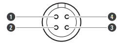 |
Four pin locking connector Pin 1: GND Pin 2: INST INPUT Pin 3: MIC INPUT Pin 4: DC BIAS +10 V |
| Battery | 3 V DC (two 1.5 V AA) |
| Operating temperature range | 5 to 40°C (41 to 104°F) |
| Battery life[1] | Approx. 15 hours (alkaline) Approx. 14 hours 30 minutes (Ni-MH) Approx. 29 hours (lithium) |
| Dimensions | 63.7 mm (2.5″) × 22.7 mm (0.89″) × 107.4 mm (4.2″) (W × D × H) |
| Weight (without batteries) | 80 g (2.8 oz) |
ATW-T1402
| Modulation mode | GFSK |
| RF output power | 10 mW EIRP |
| RF sensitivity | −90 dBm, typical |
| Antenna | True diversity |
| Microphone type | Dynamic |
| Microphone polar pattern | Hypercardioid |
| Battery | 3 V DC (two 1.5 V AA) |
| Operating temperature range | 5 to 40°C (41 to 104°F) |
| Battery life[1] | Approx. 18 hours (alkaline) Approx. 16 hours 30 minutes (Ni-MH) Approx. 35 hours (lithium) |
| Dimensions | 265.0 mm (10″) × 53.7 mm (2.1″) |
| Weight (without batteries) | 300 g (11 oz) |
| Included accessories | Mic holder AT8456a, converting thread adapter (3/8 – 5/8) |
ATW-T1406
| Modulation mode | GFSK |
| RF output power | 10 mW EIRP |
| RF sensitivity | −90 dBm, typical |
| Antenna | True diversity |
| Maximum input sound pressure level | 139 dB SPL |
| Microphone type | Condenser |
| Microphone polar pattern | Cardioid |
| Operating temperature range | 5 to 40°C (41 to 104°F) |
| Built-in battery | 3.7 V lithium-ion battery (5.5 Wh, 1,460 mAh) |
| Battery life[1] | Approx. 12 hours |
| Charging time[1] | Approx. 3 hours 10 minutes |
| USB charging port | USB Type-C (USB 2.0) |
| Dimensions | 90.5 mm (3.6″) × 129.4 mm (5.1″) × 31.9 mm (1.3″) (W × D × H) |
| Weight (with battery) | 510 g (18 oz) |
| Included accessories | USB power supply adapter, USB power supply adapter blade, USB cable (1.5 m [4.9′]) |
ATW-T1407
| Modulation mode | GFSK |
| RF output power | 10 mW EIRP |
| RF sensitivity | −90 dBm, typical |
| Antenna | True diversity |
| Microphone | Gooseneck microphone supported |
| Phantom power supply | 24 V DC |
| Operating temperature range | 5 to 40°C (41 to 104°F) |
| Built-in battery | 3.7 V lithium-ion battery (5.5 Wh, 1,460 mAh) |
| Battery life[1] | When using a gooseneck microphone with no LED: Approx. 12 hours When using a gooseneck microphone with an LED: Approx. 8 hours |
| Charging time[1] | Approx. 3 hours 10 minutes |
| USB charging port | USB Type-C (USB 2.0) |
| Dimensions | 90.5 mm (3.6″) × 129.4 mm (5.1″) × 47.6 mm (1.9″) (W × D × H) |
| Weight (with battery) | 490 g (17 oz) |
| Included accessories | USB power supply adapter, USB power supply adapter blade, USB cable (1.5 m [4.9′]) |
Trademarks
- Microsoft® andWindows® are registered trademarks of Microsoft Corporation in the United States and/or other countries.
- Microsoft Windows operating system is indicated in its abbreviated form as Windows.
- Apple and macOS are trademarks of Apple Inc., registered in the U.S. and other countries.
- USB Type-C™ is a trademark of the USB Implementers Forum.
- All other company and product names that appear in this document are trademarks or registered trademarks of their respective companies.
Systemdiagram (ATW-R1440)

Audio-Technica Corporation
2-46-1 Nishi-naruse, Machida, Tokyo 194-8666, Japan
www.audio-technica.com
©2024 Audio-Technica Corporation
Global Support Contact: www.at-globalsupport.com
351716190-02-02
ver.1 2024.05.01
ver.2 2024.09.01
Documents / Resources
 |
audio-technica System 20 PRO 2.4 GHz Wireless System [pdf] User Manual System 20 PRO 2.4 GHz Wireless System, System 20 PRO, 2.4 GHz Wireless System, Wireless System, System |