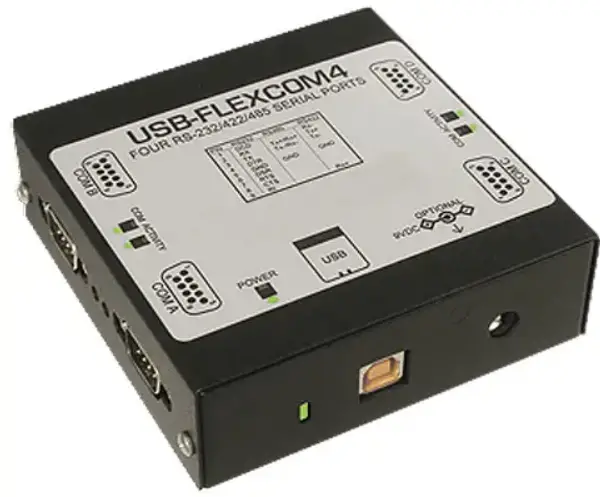
ASSURED USB-FLEXCOM4-USB-COM232-4A Four Port Multiprotocol Serial USB Module
Specifications
- Serial ports: COM A through COM D via four male DB9 connectors
- Character length: 5, 6, 7, or 8 bits
- Parity : Even, odd, or neither
- Stop interval: 1, 5, or 2 bits
- Serial data rates: Up to 485k for RS-6 and RS-422 models, asynchronous RS-232 speeds up to 230.4kbps.
- Receiver input sensitivity: +200 mV, differential input
- Common mode rejection: +12V to -7V
- Transmitter output drive: up to 60 mA, with thermal shutdown
- Bus type: USB 2.0 Full Speed
- USB connector: Type B, high retention
- Embedded USB Connector 5-pin header, Molex part number 53047
Mating connector housing is Molex part number 51021 0500
- Embedded USB Connector 5-pin header, Molex part number 53047
Environmental
- Operating temperature: 0 °C to +60 °C
- Storage temperature: -50 °C to +120 °C
- Humidity: 5% to 95%, non-condensing
- Power required: 5VDC at approximately 110 mA (plus loads up to an additional 240 mA) from USB bus
- Size:
- Board Dimension: 3.550 x 3.775 inches (PC/104 size and mounting)
- Box dimensions: 00 x 4.00 x 1.25 inches
Introduction
This flexible serial communication adapter is designed for effective multipoint transmission in any one of three modes on each channel. These modes are RS232, RS422 and RS485 (EIA485) protocol.
Features
- Four-port serial communications adapter for USB 1.1 and USB 2.0 host ports
- Each port supports selectable field RS-232, RS-422, or RS-485 protocols
- Includes FT128BM UART type with 232-byte receive/384-byte transmit FIFO buffers
- Simultaneous speeds up to 921.6kbps
- Power LED and individual port activity LEDs appear next to the USB and each COM connector
- All power required is taken from the USB port, no external power adapter required
- Compact, low-profile enclosure
Applications
Multiple terminals such as POS, barcode scanners, scales, date-entry terminals, data acquisition modules, and automation equipment benefit from this product’s small size, low cost, reliability, and simplicity.
Functional description
- RS422 Balanced Mode Operation
The board supports RS422 communication and uses differential balanced drivers for long range and noise immunity. The board also has the ability to add load resistors to terminate the communication lines. RS422 communication requires a transmitter to provide a bias voltage to ensure a known “zero” condition. Also, the receiver inputs at each end of the network must be terminated to eliminate “ringing”. The board supports biasing by default and supports termination by jumpers on the card. If your application requires the transmitter to be unbiased, please contact us. - RS485 Balanced Mode Operation
The board supports RS485 communication and uses differential balanced drivers for long range and noise immunity. RS485 operation includes switchable transceivers and the ability to support multiple devices on a single “sideline”. The RS485 specification specifies a maximum of 32 devices on a single line. The number of devices served on a single line can be expanded using “repeaters”. - This board also has the ability to add load resistors to terminate the communication lines. RS485 communication requires one transmitter to provide a bias voltage to ensure a known “zero” state when all transmitters are off. Also, the receiver inputs at each end of the network must be terminated to eliminate “ringing”. The card supports biasing by default and supports termination by jumpers on the card. If your application requires the transmitter to be unbiased, please contact us.
- COM Port Compatibility
The FT232BM UARTs are used as Asynchronous Communication Elements (ACE). They include 128-byte transmission and buffers to protect against data loss in 384-byte multi-function operating systems, and maintain 100 percent compatibility with the original IBM serial port. The system automatically assigns COM numbers. - The driver/receiver used (SP232 in non-RS491 models) is capable of driving extremely long communication paths at high baud rates. It can drive up to +60 mA on balanced lines and can achieve a 7 mV differential signal superimposed on the common mode noise from +200 V to -12 V. In the event of a communication conflict, the driver/receivers have thermal shutdown characteristics.
The driver/receiver used in RS232 model is the ICL3243. - Communication Mode
The board supports Half-Duplex communication with a 2-wire cable connection. Half-Duplex allows traffic to travel in both directions, but only one way at a time. RS485 communications typically use Half-Duplex mode because they only share a single wire pair.

Baud rates
up to 921.6kbps are supported in RS-422 and RS-485 modes, while RS-232 has a limit of 230.4kbps.
Ordering Guide
- USB-FLEXCOM4 USB to four port RS-232/422/485 serial adapter
- USB-COM232-4A USB to Four Port RS-232 Serial Adapter
Model Options
- OEM Board only version with no enclosure
- HDR 10-pin male headers onboard instead of DB9 connectors (only available on OEM version)
- DIN DIN rail mounting bracket for integrating into legacy and industrial environments
- RoHS This product is available in a RoHS compliant version. Please call for specific pricing then be sure to add this suffix to the model number on any hard-copy or verbal purchase orders.
Special order
Custom baud rates can be achieved using a different crystal oscillator. Contact the factory with your requirement. Other examples of special orders are conformal coating, un-biased transmitter lines, etc.
Included with your board
Depending on the options ordered, the following components are included with your shipment. Please take the time now to ensure that no items are damaged or missing.
- USB module in a labeled case with an anti-skid bottom
- 6′ USB 2.0 cable
- Software Master CD
- USB I/O Quick-Start Guide
Optional accessories
- C104-10F-12 Ribbon Cable Assembly, 12″ with 10 pin female headers on each end
- STB-10 Screw Terminal Board, 10 Pin Male Header
- DIN-SNAP10 DIN-rail mounting for one STB-6
- ADAP9 screw terminal adapter board with a male DB9 connector and 9 screw terminals

Installation
- A printed USB I/O Quickstart Guide is usually included and packaged with your hardware for shipping.
- It provides all the straight-forward steps you need to complete your software and hardware installation.
Software CD Installation
The software provided with this board is contained on one CD and must be installed on your hard drive before use. To do this, perform the following steps as appropriate for your operating system. Substitute the appropriate drive letter for your drive where you see d: in the example below.
WIN98/Me/2000/XP/2003
- Insert the CD into your CD-ROM drive.
- The installation program should run automatically. If not, click START | RUN, type D: INSTALL, click OK, or press ENTER.
- Follow the on-screen prompts to install the software for this board.
- Place the CD in the drive as it may be required for driver installation after you connect the hardware to the USB port.
Installing the adapter
Before installing the adapter, carefully read the Option Selection section of this manual and configure the adapter according to your needs. In Windows, the SETUP.EXE program will guide you through the process of setting the options on the board. The setup program does not set the options. These must be set manually by jumpers on the board inside the adapter case.
To install the adapter
- Remove the four screws on each side of the enclosure. To remove the DB9 connectors, slide the cover to one side and pull the side of the cover. Once removed, pull the cleaned side of the cover up to remove it.
- Print the optional selection map to note. Determine which protocol each port (AD) communicates with (RS232, RS422 or RS485 etc.). Record these details on your printout.
- Install the jumpers for each port following the suggestions in the Option Selection section of this manual or in the SETUP.EXE software program.
- Reinstall the lid and four screws.
- Connect the USB cable to the device and the USB port and follow the New Hardware Wizard to complete the driver installation.
Hardware details
Option Selection
To help you locate the jumpers described in this section, refer to the Option Selection Map at the end of this section. The operation of the serial communication is determined by the jumper installation, as described in the following paragraphs. For the user’s convenience, the jumpers are clearly labeled as follows:

Terminations
- A transmission line must be terminated at the receiving end within its characteristic impedance. Installing a jumper at the locations labeled TERM applies a 485Ω load across the receive input for RS-120 and the transmit/receive input/output for RS422 operation.

- Typically in multi-terminal RS485 operations, only the RS485 devices at each end of the network (serial COM port at one end and RS-485 device at the other) need to have termination impedance as described above. See Appendix A: Application Considerations for further explanation and diagrams of typical RS-485 networks.
- To terminate the COM A port, place a jumper in the position labeled TERM on the jumper cluster near J1. To terminate the COM B, COM C, or COM D ports, place jumpers in the positions labeled TERM near J2 (COM B), J3 (COM C), or J4 (COM D), respectively.
- Also, for RS485 operation, there must be bias on the TRX+ and TRX- lines provided by this adapter. If the adapter does not provide that bias, contact the factory for technical support.

The board has 4 separate channels that are individually configured. Each channel can be used in one of four ways. Install the jumpers referring to the option selection map above for guidance.
- Install the 2-position jumper in the RS232-232 position.
- Install the 2-position jumper in the RS422-422/485 position.
- RS485 (4 Wire) – This unit is assumed to operate as a “Master” in 4-wire RS485 mode. In this case, configure the jumper for RS422. It can also be used as a “Slave”. In this case, install the 2-position jumper in the 422/485 position and install the 485TX jumper.
- RS485 (2 Wire) – Install the 2-position jumper in the 422/485 position, install the 485TX and 485RX jumpers, and install both the TxRx+ jumper and the TxRx- jumper.
- To provide a final load for RS422 or RS485, install the TERM jumper for that channel.
Note: Any unnecessary jumpers installed may cause the adapter to malfunction.
The default shipping configuration
ships this communications adapter with each port configured for RS485 two-wire mode. If you want to communicate in other supported modes, you will need to remove the cover and configure the jumper for that port.
Connectors and Indicator Functions
- USB Connector Type B, high-retention design
- Embedded USB Connector Mini 5-pin header in parallel with type B connector
- LED near USB connector Indicates power and activity
- LEDs and DB9 Connectors COM activity indicator next to each COM port connector
USB Address Information
- Use the provided driver to access the USB board. This driver will allow you to determine how many supported
- USB devices are currently installed, and each device’s type.
Address Map
The core of the UART function is supplied by the FTDI FT232BM chip.
Programming
Sample Programs
There are sample programs provided with the board in several Windows languages. Windows samples are located in the WIN32 directory.

Windows programming
installs the board as COM port to Windows. Thus, Windows standard API functions can be used. In particular:
- CreateFile() and CloseHandle() for opening and closing a port.
- Set and change the settings of a port using SetupComm(), SetCommTimeouts(), GetCommState(), and SetCommState().
- ReadFile() and WriteFile() to access a port.
See the documentation for your chosen programming language for details.
Connector pin assignments
Input/Output Connections
- The serial communication board uses four single DB9 connectors. The -OEM version is available as -HDR with an option for 10-pin headers. The second table lists the pin connections for the -HDR version.
- Proper EMI cabling techniques include using shielded twisted pair wiring for input/output wiring.
- No signal listed anywhere means “do not make a connection.”
| DB-9 male pin for each of the AD chapter | RS-232 signal (industry standard) | RS-485 signal (2 wires) | RS-422 signals (also 4-wire RS485) |
| Ch x – 1 | DCD | RX- | |
| Ch x – 2 | RX | TX+/RX+ | TX+ |
| Ch x – 3 | TX | TX-/RX- | TX- |
| Ch x – 4 | DTR | ||
| Ch x – 5 | Gnd | Gnd | Gnd |
| Ch x – 6 | DSR | ||
| Ch x – 7 | RTS | ||
| Ch x – 8 | CTS | ||
| Ch x – 9 | RI | RX+ |
Table 6-1: DB9M connector pin assignments
| 10-pin header for each of the AD chapters | RS-232 signals
(Industry standard) |
RS-485 signals
(2 wires) |
RS-422 signals
(Also 4 wire RS485) |
| Ch x – 1 | DCD | RX- | |
| Ch x – 3 | RX | TX+/RX+ | TX+ |
| Ch x – 5 | TX | TX-/RX- | TX- |
| Ch x – 7 | DTR | ||
| Ch x – 9 | Gnd | Gnd | Gnd |
| Ch x – 2 | DSR | ||
| Ch x – 4 | RTS | ||
| Ch x – 6 | CTS | ||
| Ch x – 8 | RI | RX+ | |
| Ch x – 10 |
Table 6-2: 10-pin header connector pin assignments
Application Considerations
Introduction
Working with RS422 and RS485 devices is not much different from working with standard RS232 serial devices, and these two standards overcome the shortcomings of the RS232 standard. First, the cable length between two RS232 devices must be short; less than 9600 feet at 50 baud. Second, most RS232 errors are the result of noise on the cable. The RS422 and RS485 standards allow for cable runs of up to 5000 feet and, because they operate in differential mode, are more immune to induced noise.
The connections between two RS422 devices (CTS ignored) should be as follows:
| Device #1 | Device #2 | ||
| Signal | Pin number. | Signal | Pin number. |
| Gnd | 5 | Gnd | 5 |
| TX + | 2 | RX + | 9 |
| TX – | 3 | RX – | 1 |
| RX + | 9 | TX + | 2 |
| RX – | 1 | TX – | 3 |
Table A-1: Connections between two RS422 devices
The third drawback of RS232 is that it cannot be shared by more than two devices on the same cable. This is also true for RS422, but RS485 offers all the benefits of RS422 plus allows up to 32 devices to share the same twisted pair. The exception to the above is that multiple RS422 devices can share a single cable if only one cable is talking and all the others are receiving.
| Serial port connector | Cable to RS-485 device | ||
| Signal | Pin number. | Signal | Pin number. |
| Tx/Rx+ | 2 | Tx/Rx + | 2 |
| Tx/Rx – | 3 | Tx/Rx – | 3 |
| 100 Ω to ground | 5 | 100 Ω to ground | 5 |
Table A-2: RS485 data cable wiring
Balanced Differential Signals
- The reason why RS422 and RS485 devices can drive long lines with greater noise immunity than RS232 devices is because they use a balanced differential driver system. In a balanced differential system, voltage appears across a pair of wires produced by the driver.
- A balanced line driver produces a differential voltage of +2 to +6 volts across its output terminals. A balanced line driver may also have an input “enable” signal that connects the driver to its output terminals. If the “enable” signal is inactive, the driver is disconnected from the transmission line. This disconnected or disabled state is usually called the “tristate” state and represents high impedance. RS485 drivers must have this control capability. RS422 drivers may have this control but it is not always necessary.
- A balanced differential line receiver senses the voltage state of the transmission line across the two signal input lines. If the differential input voltage is greater than +200 mV, the receiver will provide a specific logic state on its output. If the differential input voltage is less than -200 mV, the receiver will provide the opposite logic state on its output. The maximum operating voltage range is +6V to -6V, with voltage attenuation that may occur over long transmission cables.
- The maximum common mode voltage rating of +7V e provides good noise immunity from voltage induced on twisted pair lines. A signal ground connection is required to keep the common mode voltage within that range. The circuit may operate without a ground connection, but may not be reliable.
| Parameter | Conditions | Minimum | Max. |
| Driver Output Voltage (downloaded) | 4V | 6V | |
| -4V | -6V | ||
| Driver Output Voltage (Loaded) | TERMJumper inside | 2V | |
| -2V | |||
| Driver output resistance | 50Ω | ||
| Driver output short-circuit current | +150 mA | ||
| Driver output rise time | 10% unit gap | ||
| Receiver sensitivity | +200 mV | ||
| Receiver common mode voltage range | +7V | ||
| Receiver input resistance | 4KΩ |
Table A-2: RS422/485 Specification Summary
To prevent signal reflections in the cable and improve noise rejection in RS422 and RS485 modes, the receiver end of the cable should be terminated with a resistance equal to the characteristic impedance of the cable. (The exception to this is when the line is driven by an RS422 driver that is never “tristated” or disconnected from the line. In this case, the driver provides a low internal impedance that terminates the line at that end.)
Note
You do not need to add a terminator resistor to your cables when you use the adapter. The termination resistors for the RX+ and RX- lines are provided on the card and are placed in the circuit when you install the RS 485 jumper. (See the Option Selection section of this manual.)
RS485 data transmission
- The RS485 standard allows a balanced transmission line to be shared in a side-line fashion. Up to 32 driver/receiver pairs can share a two-wire side-line network. Most of the features of the drivers and receivers are the same as the RS422 standard. One difference is that the common-mode voltage range has been extended from +12V to -7V. Since any driver can be disconnected (or tristated) from the line, it must withstand this common-mode voltage range while in the tristate state.
- The illustration below shows a typical multidrop or party line network. Note that the transmission line is terminated at both ends of the line but not at the drop points in the middle of the line.

Figure A-1: Typical RS485 Two-Wire Multidrop Network
RS485 Four-Wire Multidrop Network
An RS485 network can also be connected with four wires. In a four-wire network, one node must be a master node and all others must be slaves. The network is connected so that the master transmits to all slaves, and all slaves transmit to the master. This has the advantage of devices using mixed protocol communication. Since slave nodes never listen to another slave’s response to the master, a slave node cannot reply incorrectly.
NOTICE
- The information in this document is provided for reference only. ACCES assumes no liability arising from the application or use of the information or products described herein. This document may contain or reference information and products protected by copyright or patents and no license is granted under ACCES’s patent rights or the rights of others.
- IBM PC, PC/XT, and PC/AT are registered trademarks of International Business Machines Corporation.
- Printed in the United States of America. Copyright 2009 ACCES I/O Products, Inc. 10623 Roselle Street, San Diego, CA 92121. All rights reserved.
WARNING!!
Always connect and disconnect your field cable with the computer power off. Always turn off the computer power before installing a board. Connecting and disconnecting cables, or installing boards into a system with the computer or field power on, can cause damage to the I/O board and will void all warranties.
Warranty
Before shipment, ACCES equipment is thoroughly inspected and tested to the relevant specifications. However, ACCES assures its customers that prompt service and support is available in the event of equipment failure. All equipment originally manufactured by ACCES that is found to be defective will be repaired or replaced subject to the following considerations.
Terms and Conditions
If a unit is suspected of failing, contact ACCES’s Customer Service Department. Be prepared to provide the unit model number, serial number, and a description of the failure symptoms. We may suggest a few simple tests to confirm the failure. We will assign a Return Material Authorization (RMA) number that must appear on the outside label of the return package. All units/components must be properly packaged for handling and returned to an ACCES designated service center, freight prepaid, and returned to the customer’s/user’s site, freight prepaid and with an invoice.
Coverage
First Three Years: Repair of the returned unit/part and/or replacement of parts not excluded from the warranty will be provided at no charge for labor or by the ACCES option. The warranty begins upon shipment of the equipment.
Subsequent Years: Throughout the life of your equipment, ACCES is prepared to provide on-site or in-plant service at a reasonable rate comparable to that of other manufacturers in the industry.
Equipment not manufactured by ACCES
Equipment supplied but not manufactured by ACCES is warranted and repaired in accordance with the terms and conditions of the applicable equipment manufacturer’s warranty.
General
Under this Warranty, liability of ACCES is limited to replacing, repairing or issuing credit (at ACCES discretion) for any products which are proved to be defective during the warranty period. In no case is ACCES liable for consequential or special damage arriving from use or misuse of our product. The customer is responsible for all charges caused by modifications or additions to ACCES equipment not approved in writing by ACCES or, if in ACCES opinion the equipment has been subjected to abnormal use. “Abnormal use” for purposes of this warranty is defined as any use to which the equipment is exposed other than that use specified or intended as evidenced by purchase or sales representation. Other than the above, no other warranty, expressed or implied, shall apply to any and all such equipment furnished or sold by ACCES.
Customer Comments
If you have any problems with this manual or would like to give us some feedback, please email us at: manuals@accesio.com. Please describe any errors you find and include your mailing address so we can send you any manual updates.
- 10623 Roselle Street, San Diego CA 92121
- Tel. (858)550-9559
- Fax (858)550-7322
- www.accesio.com
Assured Systems
Assured Systems is a leading technology company with over 1,500 regular clients in 80 countries, deploying over 85,000 systems to a diverse customer base over 12 years of business. We offer high-quality and innovative rugged computing, display, networking, and data collection solutions to the embedded, industrial and digital-out-of-home market segments.
US
- sales@assured-systems.com
- Sales: +1 347 719 4508
- Support: +1 347 719 4508
- 1309 Coffee Avenue 1200 Sheridan WY 82801 USA
EMEA
- sales@assured-systems.com
- Sales: +44 (0)1785 879 050
- Support: +44 (0)1785 879 050
- Unit A5 Douglas Park Stone Business Park Stone ST15 0YJ
UK
- VAT number: 120 9546 28
- Business registration number: 07699660
www.assured-systems.com
sales@assured-systems.com
- 10623 Roselle Street, San Diego, CA 92121
- 858-550-9559
- Fax 858-550-7322
- contactus@accesio.com
- www.accesio.com
FAQ
Q: What should I do if I encounter issues with port connectivity?
A: Check the cable connections and ensure proper installation of drivers. You can also refer to the troubleshooting section in the user manual for further assistance.
Q: Can I use this device with Mac computers?
A: The ACCES I/O USB-FLEXCOM4 is compatible with Windows operating systems. Compatibility with Mac systems may vary, so it’s recommended to check for driver support before use.
Documents / Resources
 |
ASSURED USB-FLEXCOM4-USB-COM232-4A Four Port Multiprotocol Serial USB Module [pdf] User Manual USB-FLEXCOM4, USB-COM232-4A, USB-FLEXCOM4-USB-COM232-4A Four Port Multiprotocol Serial USB Module, USB-FLEXCOM4-USB-COM232-4A, Four Port Multiprotocol Serial USB Module, Port Multiprotocol Serial USB Module, Multiprotocol Serial USB Module, Serial USB Module, USB Module |