
1. Introduction
This manual provides comprehensive instructions for the installation, operation, maintenance, and troubleshooting of the BQHHWTZ EPC-A18 Servo Line Edge Position Control System. This system is designed for precise web guiding applications in commercial manufacturing, ensuring accurate material alignment using an ultrasonic sensor and a 150mm stroke actuator.
2. Safety Information
WARNING:
- Always disconnect power before performing any installation, maintenance, or troubleshooting.
- Ensure all electrical connections are made by qualified personnel and comply with local electrical codes.
- Do not operate the system with damaged components.
- Keep hands and loose clothing away from moving parts during operation.
- The system operates on AC220V. Exercise extreme caution to prevent electrical shock.
3. Components Overview
The EPC-A18 system consists of several key components working in conjunction to achieve precise web guiding. Refer to the diagram below for a visual representation of the system components.
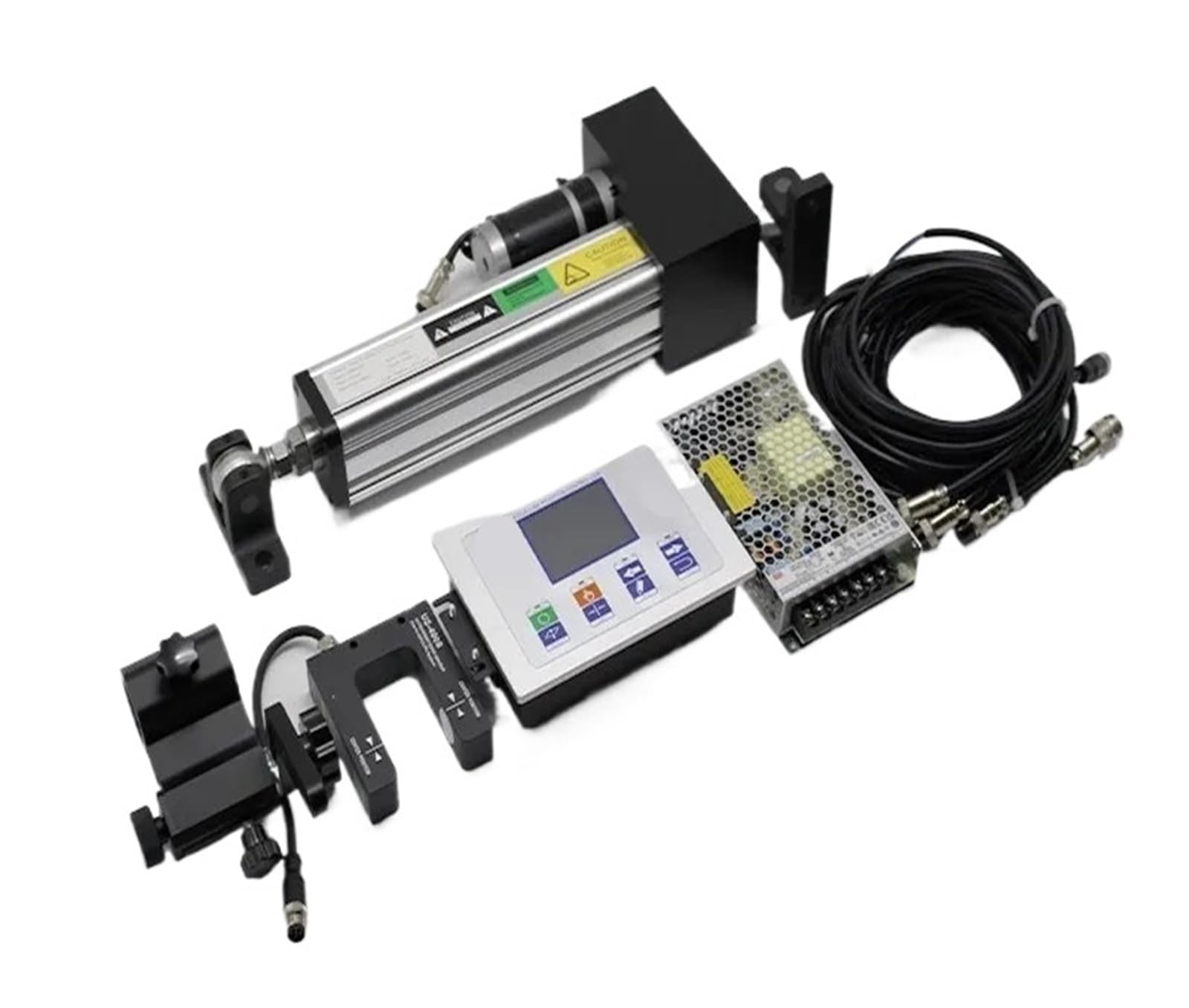
Figure 3.1: EPC-A18 System Components. This image displays the main components of the EPC-A18 system. It includes the central EPC-A18 controller with its display and control buttons, a blue photoelectric sensor (JULONG ZIK), two U-shaped ultrasonic edge sensors (JULONG US-400S and PS-400S), a linear actuator, and a web guiding mechanism. Yellow lines indicate connections between the components, illustrating the system's integrated nature.
- EPC-A18 Controller: The central processing unit with a display and control buttons (AUTO, MAN, LEFT, RIGHT, DETECT, CENT, SET, ESC) for system configuration and operation.
- Ultrasonic Edge Sensors (US-400S/PS-400S): U-shaped sensors that detect the edge position of the web material using ultrasonic technology.
- Photoelectric Sensor (JULONG ZIK): An additional sensor, typically used for line or edge detection based on light.
- Linear Actuator: A mechanical device that provides the precise linear movement (150mm stroke) required to adjust the web position.
- Web Guiding Mechanism: The physical structure that moves the web material based on the actuator's input.
4. Setup
- Mounting the Controller: Securely mount the EPC-A18 controller in an accessible location, away from excessive vibration or heat.
- Installing Sensors:
- Mount the ultrasonic edge sensors (US-400S/PS-400S) to detect the web edge accurately. Ensure they are positioned perpendicular to the web's travel direction.
- If using, install the photoelectric sensor (JULONG ZIK) according to its specific requirements for line or edge detection.
- Actuator Installation: Connect the linear actuator to the web guiding mechanism. Ensure the 150mm stroke range is sufficient for your application and that the actuator moves freely.
- Wiring Connections:
- Connect the sensors to the appropriate input ports on the EPC-A18 controller.
- Connect the linear actuator to the output control port of the EPC-A18 controller.
- Connect the AC220V power supply to the EPC-A18 controller. Verify all connections are secure and correct before applying power.
- Initial Power-Up: Apply power to the system. The controller display should illuminate.
5. Operating Instructions
The EPC-A18 controller offers both automatic and manual operation modes.
5.1. Controller Interface
- AUTO Button: Switches the system to automatic web guiding mode.
- MAN Button: Switches the system to manual control mode.
- LEFT / RIGHT Buttons: In manual mode, these buttons move the web guiding mechanism left or right.
- DETECT Button: Initiates the sensor detection and calibration process.
- CENT Button: Centers the web guiding mechanism.
- SET Button: Enters the system settings menu for parameter adjustment.
- ESC Button: Exits the current menu or cancels an operation.
5.2. Calibration and Setup
- Sensor Calibration:
- Place the web material in its intended path.
- Press the DETECT button on the controller. Follow the on-screen prompts to calibrate the ultrasonic sensors to the web edge. This typically involves moving the web or sensor to define the edge limits.
- Setting Parameters:
- Press the SET button to access system parameters.
- Adjust sensitivity, response speed, and other guiding parameters as required for your specific material and application. Refer to the on-screen menu for detailed options.
- Save settings before exiting.
5.3. Automatic Operation
After successful calibration and parameter setup:
- Press the AUTO button.
- The system will now automatically monitor the web edge position using the sensors and adjust the linear actuator to maintain the desired alignment.
- Monitor the display for real-time feedback on web position and system status.
5.4. Manual Operation
For fine adjustments or initial positioning:
- Press the MAN button.
- Use the LEFT and RIGHT buttons to manually move the web guiding mechanism.
- Press the CENT button to return the mechanism to its central position.
6. Maintenance
- Cleaning: Regularly clean the sensor surfaces to ensure accurate detection. Use a soft, dry cloth. Avoid abrasive cleaners.
- Inspection: Periodically inspect all cables and connections for wear or damage. Ensure all mounting hardware is secure.
- Actuator Lubrication: Check the linear actuator for smooth operation. Lubricate moving parts according to the actuator's specific maintenance guidelines, if applicable.
- Software Updates: Check the manufacturer's website for any available firmware or software updates for the EPC-A18 controller.
7. Troubleshooting
| Problem | Possible Cause | Solution |
|---|---|---|
| System not powering on | No power supply; loose power connection; faulty power cable. | Check AC220V power source. Ensure power cable is securely connected. Test with a different power cable if available. |
| Inaccurate web guiding | Sensors misaligned or dirty; incorrect calibration; parameters not optimized. | Clean sensor surfaces. Re-calibrate sensors using the DETECT button. Adjust sensitivity and response speed in SET menu. |
| Actuator not responding | Loose actuator connection; faulty actuator; system in manual mode. | Check actuator cable connection to controller. Ensure system is in AUTO mode. Test actuator in MAN mode. |
| Controller display blank or frozen | Power issue; software error. | Cycle power to the controller. If issue persists, contact support. |
8. Specifications
| Feature | Detail |
|---|---|
| Model Number | EPC-A18 (Item Model Number: BYSSLWWCX) |
| Brand | BQHHWTZ |
| Input Voltage | AC220V |
| Sensor Type | Ultrasonic (US-400S/PS-400S) |
| Actuator Stroke | 150mm |
| Material | Carbide (for certain components, as per product description) |
| Use | Commercial Manufacture |
| Item Weight | 1.76 ounces (approx. 50 grams) |
| Package Dimensions | 0.39 x 0.39 x 0.39 inches (approx. 1x1x1 cm) |
9. Warranty and Support
Specific warranty details are not provided in the product information. For warranty claims, technical support, or service inquiries, please contact your vendor or the manufacturer, BQHHWTZ, directly. Ensure you have your product model number (EPC-A18) and item model number (BYSSLWWCX) available when contacting support.


