
1. Introduction
This manual provides detailed instructions for the installation, operation, and maintenance of your JINGSHA H311 LGA1151 Motherboard. Designed for desktop applications, this motherboard supports Intel 6th, 7th, 8th, and 9th generation processors and DDR4 memory, offering a stable and efficient platform for various computing needs, including gaming and office use.
Key features include a premium layout for enhanced performance, advanced technology for data signal integrity, and support for M.2 NVMe/NGFF storage solutions. It also features an upgraded network solution for reliable connectivity and a robust thermal design for system stability.

Figure 1: Front view of the JINGSHA H311 LGA1151 Motherboard, showcasing the CPU socket, RAM slots, and various connectors.
2. Setup and Installation
Before beginning installation, ensure your system is powered off and disconnected from the power source. Handle components with care and use anti-static precautions to prevent damage.
2.1 CPU Installation
- Locate the LGA1151 CPU socket on the motherboard.
- Gently push down the load lever and pull it to the side to open the CPU socket.
- Align the triangular mark on your Intel LGA1151 processor with the corresponding mark on the socket. Carefully place the CPU into the socket without forcing it.
- Close the load plate and push the load lever back into its locked position.
- Install the CPU cooler according to its manufacturer's instructions.
2.2 RAM Installation
- Locate the two DDR4 DIMM slots on the motherboard.
- Open the clips at both ends of the DIMM slot.
- Align the notch on the DDR4 memory module with the key in the DIMM slot.
- Insert the memory module firmly into the slot until the clips snap into place. Ensure both clips are closed.
2.3 Storage Device Installation
M.2 SSD Installation
- Locate the M.2 2280 slot on the motherboard.
- Remove the M.2 standoff screw.
- Insert the M.2 SSD into the slot at a 30-degree angle.
- Gently push down the M.2 SSD and secure it with the standoff screw.
SATA Drive Installation
- Connect one end of a SATA data cable to a SATA 3.0 port on the motherboard.
- Connect the other end of the SATA data cable to your SATA hard drive or SSD.
- Connect a SATA power cable from your power supply unit (PSU) to the SATA drive.
2.4 Connecting Peripherals and Power
Connect the necessary cables to the motherboard:
- 24-pin ATX Power Connector: Connect the main power cable from your PSU.
- 8-pin 12V CPU Power Connector: Connect the CPU power cable from your PSU.
- Front Panel Connectors: Connect the power switch, reset switch, HDD LED, and front panel audio/USB headers according to the motherboard manual or markings.
- USB Ports: Connect USB devices to the available USB 2.0 and USB 3.0 ports on the back panel.
- Display Outputs: Connect your monitor to either the HDMI or VGA port on the back panel.
- Network: Connect an Ethernet cable to the RJ45 LAN port.
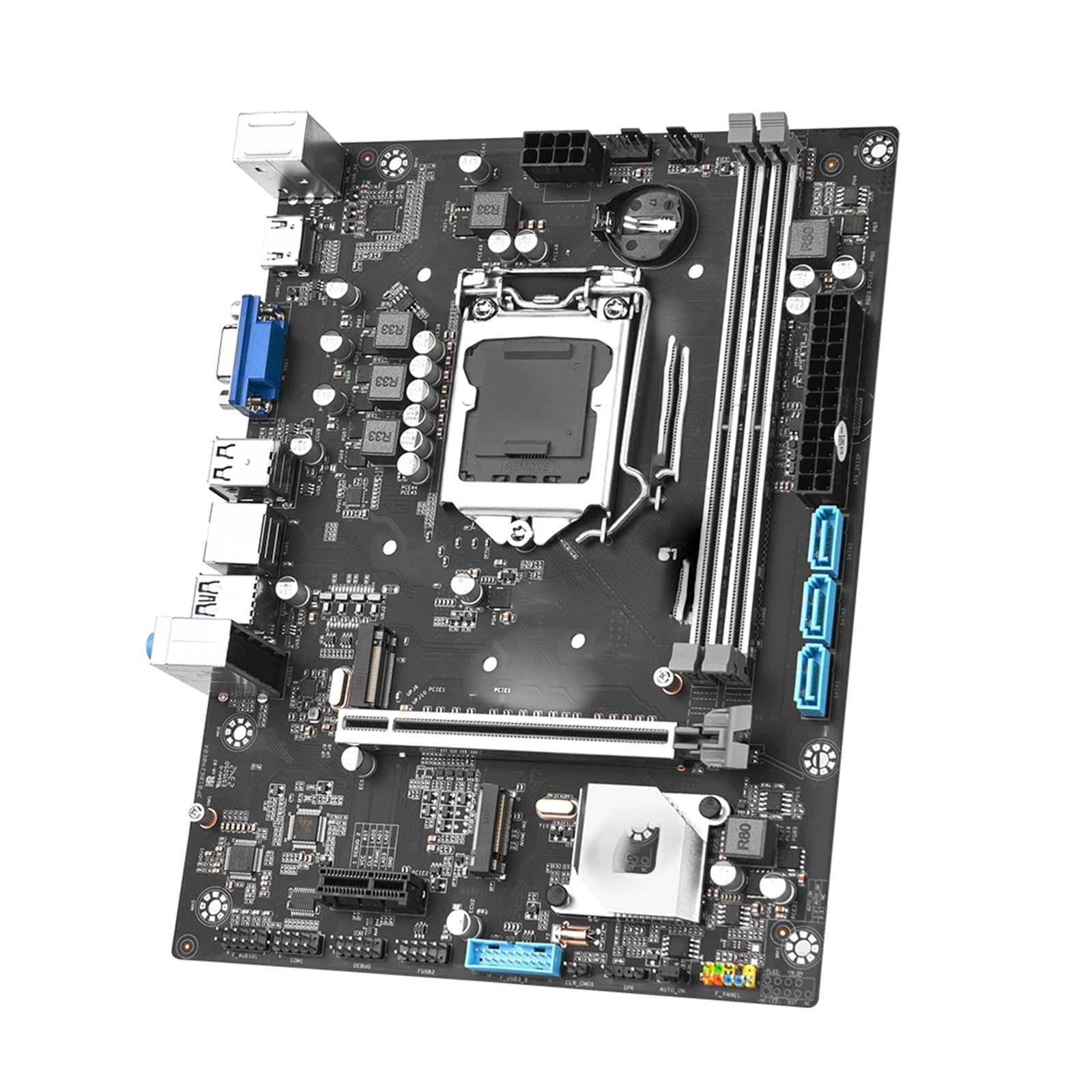
Figure 2: Back view of the JINGSHA H311 LGA1151 Motherboard, showing the CPU backplate and mounting holes.

Figure 3: Rear I/O panel of the JINGSHA H311 LGA1151 Motherboard, featuring USB, video, audio, and LAN ports.
3. Operating Instructions
3.1 First Boot and BIOS Setup
- After connecting all components and power, press the power button on your PC case.
- During the boot process, repeatedly press the DEL or F2 key (check your system's specific key) to enter the BIOS/UEFI setup utility.
- In the BIOS, you can configure various settings such as boot order, system time, CPU settings, and memory profiles.
- Ensure your storage devices are recognized and set the primary boot device to your operating system drive.
- Save changes and exit the BIOS to continue booting into your operating system.
3.2 Driver Installation
After installing your operating system, install the necessary drivers for the motherboard chipset, integrated graphics (if used), LAN, and audio. These drivers are typically provided on a support CD or can be downloaded from the manufacturer's website.
4. Maintenance
4.1 Cleaning
- Regularly clean dust from your PC case and motherboard components using compressed air.
- Ensure the system is powered off and unplugged before cleaning.
- Avoid using liquid cleaners directly on components.
4.2 BIOS/UEFI Updates
Periodically check the manufacturer's website for BIOS/UEFI updates. Updates can improve system stability, compatibility, and performance. Follow the provided instructions carefully when performing a BIOS update.
5. Troubleshooting
This section addresses common issues you might encounter.
| Problem | Possible Cause | Solution |
|---|---|---|
| System does not power on | Loose power cables, faulty PSU, incorrect front panel connections. | Check 24-pin ATX and 8-pin CPU power connections. Verify front panel power switch connection. Test PSU if possible. |
| No display output | Monitor not connected, incorrect display output, faulty RAM/CPU. | Ensure monitor is connected to the correct port. Reseat RAM and CPU. Try one RAM stick at a time. |
| Operating system not found | Incorrect boot order, unformatted drive, faulty drive. | Check BIOS boot order. Ensure OS is installed on the drive. Verify drive connections. |
| System instability/crashes | Overheating, faulty components, outdated drivers. | Monitor temperatures. Reseat components. Update drivers and BIOS. |
6. Technical Specifications
| Feature | Specification |
|---|---|
| Model | H311M-K LGA1151 |
| Processor Socket | Intel LGA1151 (Supports GEN 6/7/8/9) |
| Chipset | Intel H110 |
| Memory | 2 x UDIMM DDR4 slots, Dual Channel, 1866/2133/2400/2666MHz (CPU dependent), Max. 32GB |
| Display Outputs | 1 x HDMI (Supports 4K/30Hz), 1 x VGA |
| Storage | 3 x SATA 3.0 Ports, 1 x M.2 2280 NVMe x4 Port, 1 x M.2 2280 NGFF SATA SSD Port |
| USB Ports | 4 x USB 2.0 Ports (2 rear, 2 via header), 4 x USB 3.0 Ports (2 rear, 2 via header) |
| Expansion Slots | 1 x PCIe 3.0 x16 slot, 1 x PCIe 3.0 x1 slot |
| Back Panel Connectors | 1 x HDMI, 1 x VGA, 2 x USB 3.0, 2 x USB 2.0, 1 x RJ45 LAN, Audio Jacks |
| Onboard Connectors | CPU FAN, SYS FAN, Front Audio, USB 3.0 Header, USB 2.0 Header, RS232 COM Header, Front Control Panel, Speaker Header, 24-pin ATX Power, 8-pin 12V Power |
| Form Factor | Micro-ATX (223mm x 170mm) |
| Application | Desktop |
7. Warranty and Technical Support
7.1 Warranty Information
The manufacturer's warranty for this product is not specified. Please refer to your retailer or point of purchase for any applicable warranty details.
7.2 Technical Support
For technical assistance, please contact your product vendor or refer to their official support channels. Ensure you have your product model and purchase information ready when seeking support.
