
ACEIRMC ESP32-S3 Supermini
ACEIRMC Type-C Supermini ESP32-S3 Development Board User Manual
Model: ESP32-S3 Supermini
1. Introduction
The ACEIRMC Type-C Supermini ESP32-S3 Development Board is a compact, high-performance, and cost-effective IoT mini development board designed for low-power IoT applications and wireless wearable projects. Featuring the powerful ESP32-S3 chip, it offers robust processing capabilities, Wi-Fi, and Bluetooth connectivity, making it suitable for a wide range of embedded systems and prototyping.
2. Safety Information
Please read and understand the following safety precautions before using the development board:
- Handle with Care: This is a sensitive electronic device. Avoid dropping or subjecting it to strong impacts.
- Power Supply: Use only appropriate power sources (5V DC via USB-C or VIN pin). Exceeding the recommended voltage can damage the board.
- Static Electricity: Discharge any static electricity from your body before handling the board to prevent damage to sensitive components.
- Environment: Operate the board in a dry environment. Avoid exposure to moisture, extreme temperatures, or corrosive substances.
- Soldering: If soldering is required for pin headers or other components, ensure proper ventilation and use appropriate safety equipment.
- Modifications: Unauthorized modifications to the board may void any potential warranty and could lead to malfunction or damage.
3. Package Contents
Verify that all items are present in your package:
- 1 x ACEIRMC Type-C Supermini ESP32-S3 Development Board
- 2 x Pin Headers (unassembled, for user soldering)

Image: The Type-C Supermini ESP32-S3 Development Board shown with the two included pin headers, ready for assembly.
4. Board Overview
The ESP32-S3 Supermini board features a compact design with essential components for development. Below is an overview of its key features and pinout.
4.1. Key Components
- ESP32-S3 Chip: The main microcontroller unit, providing Wi-Fi, Bluetooth, and processing power.
- USB Type-C Port: For power supply, data communication (UART), and firmware uploading.
- BOOT Button: Used in conjunction with the RST button for entering bootloader mode to upload new firmware.
- RST (Reset) Button: Resets the ESP32-S3 chip.
- GPIO Pins: General Purpose Input/Output pins for connecting external sensors, actuators, and other peripherals.
- RGB LED: An onboard RGB LED for status indication or user-defined functions.
- Blue LED: An onboard blue LED, typically connected to a general-purpose I/O pin (GPIO48).
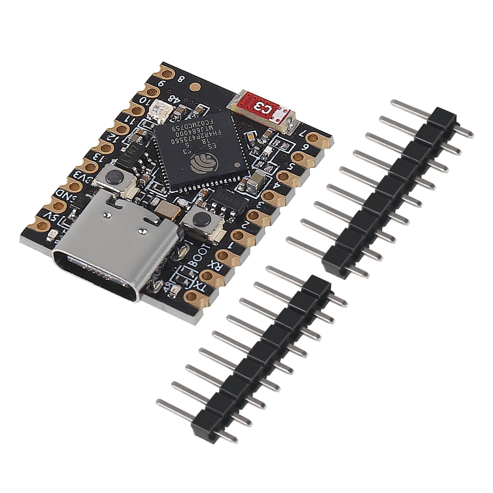
Image: Front and back views of the ESP32-S3 Supermini board, showing the USB-C port, ESP32-S3 chip, buttons, and pin labels.

Image: Detailed close-ups highlighting the ESP32-S3 chip, the Type-C USB connector, and the various pin connections on the board.
4.2. Dimensions
The board is ultra-small, measuring approximately 22.52mm x 18mm.

Image: The ESP32-S3 Supermini board with its dimensions clearly marked as 23mm (0.90inch) by 18mm (0.70inch), alongside the included pin headers.
5. Setup Guide
Follow these steps to set up your ESP32-S3 Supermini Development Board:
5.1. Soldering Pin Headers (Optional but Recommended)
The included pin headers are not pre-soldered. For easy prototyping with breadboards or jumper wires, it is highly recommended to solder the pin headers to the board. Ensure proper alignment before soldering.
5.2. Driver Installation
The ESP32-S3 typically uses a USB-to-UART bridge chip (e.g., CP210x or CH340) for communication. Most modern operating systems will automatically install the necessary drivers when you connect the board. If not, you may need to manually install drivers:
- Windows/macOS: Search for "CP210x driver" or "CH340 driver" online and download from the official Silicon Labs or WCH website, respectively.
- Linux: Drivers are usually built into the kernel.
5.3. IDE Setup (Arduino IDE Example)
The ESP32-S3 Supermini is compatible with the Arduino IDE. Follow these steps to prepare your development environment:
- Install Arduino IDE: Download and install the latest version of the Arduino IDE from arduino.cc.
- Add ESP32 Board Manager URL: Go to File > Preferences (or Arduino > Preferences on macOS). In the "Additional Board Manager URLs" field, add: https://raw.githubusercontent.com/espressif/arduino-esp32/gh-pages/package_esp32_index.json
- Install ESP32 Boards: Go to Tools > Board > Board Manager.... Search for "ESP32" and install the "esp32 by Espressif Systems" package.
- Select Board: Go to Tools > Board > ESP32 Arduino and select the appropriate board, such as "ESP32S3 Dev Module" or a similar ESP32-S3 option.
- Select Port: Connect the ESP32-S3 Supermini to your computer using a USB Type-C cable. Go to Tools > Port and select the serial port corresponding to your connected board.

Image: The ESP32-S3 Supermini board with its Type-C USB port prominently displayed, indicating the connection point for power and data.
6. Operating Instructions
Once your development environment is set up, you can start programming and operating your ESP32-S3 Supermini.
6.1. Uploading Your First Sketch (Arduino IDE)
- Open an Example: In the Arduino IDE, go to File > Examples > 01.Basics > Blink. This will open a new sketch.
- Modify for ESP32-S3: The Blink sketch typically uses `LED_BUILTIN`. For the ESP32-S3 Supermini, you might need to identify the GPIO pin connected to the onboard LED (e.g., GPIO48 for the blue LED, or experiment with the RGB LED pins if available in your board definition). Replace `LED_BUILTIN` with the correct GPIO number.
- Compile: Click the "Verify" button (checkmark icon) to compile the sketch.
- Upload: Click the "Upload" button (right arrow icon). If the upload fails, you might need to manually put the board into bootloader mode: press and hold the BOOT button, then press and release the RST button, then release the BOOT button. The upload should then proceed.
- Monitor Serial Output: Open the Serial Monitor (Tools > Serial Monitor) to view any output from your program. Ensure the baud rate matches the one set in your sketch (e.g., 115200).
6.2. Wi-Fi and Bluetooth Connectivity
The ESP32-S3 supports 2.4GHz Wi-Fi (802.11b/g/n) and Bluetooth 5.0. You can use the respective libraries in the Arduino IDE (e.g., `WiFi.h` and `BluetoothSerial.h`) to implement wireless communication in your projects. Refer to the extensive ESP32 documentation and examples for detailed usage.
7. Maintenance
Proper care will ensure the longevity of your development board:
- Cleaning: Use a soft, dry, anti-static cloth to clean the board. Avoid using liquids or abrasive cleaners.
- Storage: Store the board in an anti-static bag or container when not in use, especially if pin headers are not soldered, to prevent short circuits or damage.
- Firmware Updates: Regularly check for updates to the ESP32 Arduino core or Espressif SDK to benefit from new features, bug fixes, and performance improvements.
- Avoid Overloading: Do not draw excessive current from the GPIO pins or power rails, as this can damage the board. Consult the ESP32-S3 datasheet for current limits.
8. Troubleshooting
Here are some common issues and their solutions:
- Board Not Detected:
- Ensure the USB Type-C cable is fully inserted and functional.
- Check if the necessary USB-to-UART drivers are installed correctly (see Section 5.2).
- Try a different USB port on your computer.
- Upload Fails:
- Verify that the correct board and serial port are selected in the Arduino IDE (Tools > Board and Tools > Port).
- Manually put the board into bootloader mode before uploading: press and hold BOOT, press and release RST, then release BOOT.
- Ensure no other application is using the serial port.
- No Serial Monitor Output:
- Confirm the baud rate in the Serial Monitor matches the `Serial.begin()` rate in your sketch.
- Ensure `Serial.print()` statements are correctly placed in your code.
- Wi-Fi/Bluetooth Connection Issues:
- Double-check Wi-Fi SSID and password.
- Ensure the antenna is not obstructed (if external).
- Check for interference from other 2.4GHz devices.
9. Specifications
| Feature | Description |
|---|---|
| Microcontroller | ESP32-S3 (32-bit single-core RiSC-V processor) |
| Clock Speed | Up to 160MHz |
| Wi-Fi | 802.11 b/g/n, 2.4GHz (Station mode, SoftAP mode, SoftAP+Station mode, Hybrid mode) |
| Bluetooth | Bluetooth 5.0 (BLE) |
| SRAM | 400KB |
| ROM | 384KB |
| Flash Memory | 4MB (built-in) |
| Deep Sleep Power Consumption | Approximately 43μA |
| Interfaces | 1x I2C, 1x SPI, 2x UART, 11x GPIO (PWM capable), 4x ADC |
| Onboard Components | RGB LED, Blue LED (GPIO48) |
| USB Connector | USB Type-C |
| Dimensions | 22.52mm x 18mm (approx. 0.90 x 0.70 inches) |
| Security Features | AES-128/256, Hash, RSA, HMAC, Digital Signature, Secure Boot |
| Brand | ACEIRMC |
| UPC | 687117754707 |
10. Warranty and Support
Specific warranty information for this product is not provided in the available data. For warranty claims, technical support, or further assistance, please contact the seller or manufacturer directly through the platform where the product was purchased.
Ask a question about this manual
Ask about setup, troubleshooting, compatibility, parts, safety, or missing instructions. Manuals+ will review the question and use this page’s manual context to help answer it.