
Important Safety Instructions
Read and understand all safety warnings and instructions before operating this hydraulic press. Failure to follow these instructions may result in serious injury or property damage. Keep this manual for future reference.
- Always wear appropriate personal protective equipment, including safety glasses, gloves, and steel-toed boots.
- Ensure the press is placed on a stable, level surface capable of supporting its weight and the workpiece.
- Do not exceed the rated capacity of 25 tons.
- Keep hands and body clear of the ram and workpiece during operation.
- Disconnect power before performing any maintenance, adjustments, or cleaning.
- Ensure all fasteners are securely tightened before each use.
- Do not modify the press in any way. Use only original replacement parts.
- Keep the work area clean and well-lit.
- Never operate the press under the influence of drugs, alcohol, or medication.
General Information
The KAKA INDUSTRIAL HP-25F is a 25-ton H-frame electric hydraulic shop press designed for various industrial and workshop applications. It features a foot pedal for convenient operation, a 9.84-inch ram stroke, and a pressure gauge for accurate force monitoring. This press is suitable for tasks such as bending, forming, pressing, punching, staking, clamping, and straightening.
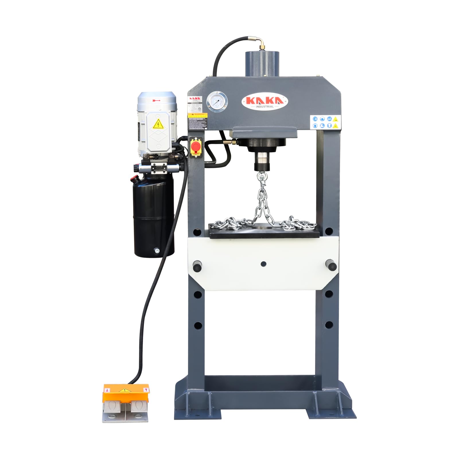
Overall view of the KAKA INDUSTRIAL HP-25F 25-Ton Electric Hydraulic Shop Press, showcasing its H-frame design, motor, hydraulic cylinder, and foot pedal.
Setup and Assembly
Unpacking
Carefully unpack all components from the shipping crate. Inspect for any damage that may have occurred during transit. Report any damage to the carrier immediately. Ensure all parts listed in the packing list are present before proceeding with assembly.
Assembly Steps
- Frame Assembly: Assemble the H-frame components according to the provided diagrams, ensuring all bolts are finger-tightened initially.
- Secure Frame: Once the frame is aligned, securely tighten all bolts using appropriate wrenches.
- Install Hydraulic Unit: Mount the hydraulic pump and motor assembly to the designated location on the press frame. Connect all hydraulic hoses, ensuring they are free from kinks and properly sealed.
- Install Work Table: Insert the bed support pins into the desired height adjustment holes on the frame. Place the work table onto the support pins.
- Connect Foot Pedal: Connect the foot pedal control cable to the main electrical control box on the press.

Side view of the hydraulic press, illustrating the mounted electric motor and hydraulic pump assembly.
Electrical Connection
The HP-25F press is equipped with a 220V single-phase gear pump (CBN2.0). Ensure the power supply matches the press's requirements. Connect the press to a dedicated, properly grounded electrical circuit. Consult a qualified electrician if you are unsure about the electrical connection.
Operating Instructions
Controls Overview
- Foot Pedal: Provides hands-free control for ram extension and retraction. Pressing one side extends the ram, the other side retracts it.
- Pressure Gauge: Displays the current hydraulic pressure being applied by the ram. It is a fluid-filled dual-scale gauge for accurate readings.
- Directional Control Valve: Located near the hydraulic pump, this valve allows for manual control of ram movement if needed, and typically has 'GO UP' and 'DOWN' positions.

The foot pedal control allows for hands-free operation of the hydraulic ram, with distinct sections for extending and retracting.

Detail of the hydraulic control valve and motor assembly, showing the 'GO UP' and 'DOWN' indicators for ram movement.
Basic Operation
- Power On: Ensure the press is properly connected to the electrical supply and turn on the main power switch.
- Adjust Work Table Height: Adjust the work table to the desired height using the bed support pins. The press has 4 bed adjustment holes spaced 5.31 inches apart. Ensure the pins are fully seated and the table is level.
- Position Workpiece: Place the workpiece securely on the work table. Ensure it is centered under the ram and stable.
- Initiate Pressing: Slowly press the 'DOWN' side of the foot pedal to extend the ram. Observe the pressure gauge to monitor the applied force.
- Hold Pressure (if needed): Maintain pressure as required for the task.
- Release Pressure: Press the 'UP' side of the foot pedal to retract the ram. Once the ram is fully retracted, remove the workpiece.

The work table of the hydraulic press, demonstrating how a workpiece (represented by a chain) can be positioned for pressing operations.
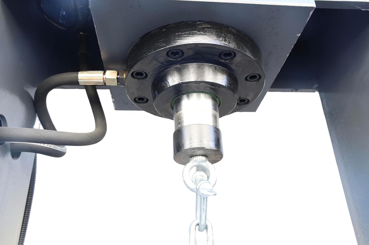
A detailed view of the hydraulic ram and cylinder assembly, showing the robust construction designed for heavy-duty pressing.
Maintenance
Regular maintenance ensures the longevity and safe operation of your hydraulic press. Always disconnect power before performing any maintenance.
Regular Checks (Before Each Use)
- Hydraulic Fluid Level: Check the hydraulic fluid reservoir level. Ensure it is within the recommended range. The reservoir capacity is 8 liters.
- Hose and Fitting Inspection: Inspect all hydraulic hoses and fittings for leaks, cracks, or damage. Replace any damaged components immediately.
- Fastener Tightness: Verify that all bolts and fasteners are securely tightened.
- Ram and Work Table Condition: Check the ram and work table for any signs of wear, damage, or deformation.
Hydraulic Fluid Replacement
Replace hydraulic fluid annually or as recommended by the manufacturer. Use only high-quality hydraulic oil specified for industrial presses. Consult the manufacturer's guidelines for the correct fluid type and replacement procedure.
Cleaning
Keep the press clean and free from debris, especially around the hydraulic components and electrical connections. Use a clean cloth to wipe down surfaces. Avoid using harsh chemicals that could damage paint or seals.
Troubleshooting Guide
| Problem | Possible Cause | Solution |
|---|---|---|
| Press does not operate | No power supply Emergency stop engaged Faulty foot pedal | Check power connection and circuit breaker Release emergency stop button Inspect foot pedal wiring; replace if necessary |
| Ram does not extend/retract smoothly | Low hydraulic fluid Air in hydraulic system Damaged hydraulic cylinder/pump | Check and refill hydraulic fluid Bleed the hydraulic system (consult service manual) Contact qualified service personnel |
| Loss of pressure | Hydraulic leak Faulty relief valve Worn pump seals | Inspect hoses and fittings for leaks; tighten or replace Have relief valve inspected/replaced by professional Contact qualified service personnel |
| Excessive noise during operation | Low hydraulic fluid Air in hydraulic system Loose components | Check and refill hydraulic fluid Bleed the hydraulic system Inspect and tighten all fasteners |
Technical Specifications
| Specification | Value |
|---|---|
| Model | HP-25F |
| Pressure Capacity | 25 tons |
| Ram Maximum Stroke | 9.84 inches |
| Ram Diameter | 4.92 inches |
| Maximum Distance to Table | 20.08 inches |
| Base Size | 11-5/6 × 10-1/4 inches |
| Bed Support Pin Diameter | 1.358 inches |
| Number of Bed Adjustment Holes | 4 |
| Bed Adjustment Hole Spacing | 5.31 inches |
| Pump Type | Gear pump CBN2.0 |
| Reservoir Capacity | 8 Liters |
| Power Requirement | 220V Single-Phase (implied by pump type) |
| Product Dimensions (L x W x H) | 42 x 20 x 69 inches |
| Item Weight | 661 pounds |
| Material | Metal |
Warranty Information
KAKA INDUSTRIAL products are manufactured to high-quality standards. For specific warranty terms and conditions, please refer to the official KAKA INDUSTRIAL website or contact customer support. Keep your purchase receipt as proof of purchase for any warranty claims.
Customer Support
For technical assistance, parts, or service inquiries, please contact KAKA INDUSTRIAL customer support. Contact information can typically be found on the official KAKA INDUSTRIAL website or on your product packaging.