
1. Introduction
This manual provides detailed instructions for the installation, operation, and maintenance of your Klanata Smart Thermostat BHT-8000-RF-VA-GBW. This device is designed for precise temperature control in boiler heating systems, offering programmable schedules and smart integration capabilities for enhanced comfort and energy management.

Figure 1: Klanata Smart Thermostat Display Unit. The sleek black display shows current temperature, set temperature, time, and various status icons.
2. Package Contents
Please verify that all items listed below are included in your package:
- 1 x Temperature Controller Display
- 1 x Temperature Controller Receiver
- 1 x Supply Cord
- 1 x Bracket
- 2 x Screws
- 2 x Wall Plugs
- 1 x User Manual (this document)
3. Product Features
- Versatile System Application: Suitable for electric heating, water heating, and wall-mounted boilers in various environments.
- Precise Temperature Regulation: Maintains temperature control accuracy of 0.5°C with power failure protection.
- Flexible Wireless Installation: No reserved cassette or surface punching required; the control panel can be moved freely.
- Automated Programming Schedules: Programmable mode with six daily time settings for energy management.
- Smart Integration Capabilities: Supports remote operation via mobile application and compatibility with smart speakers (Tmall Genie, Yandex Alice, Duer OS).
4. Safety Information
Please read and understand all safety instructions before installation and operation. Failure to follow these instructions may result in electric shock, fire, or property damage.
- Installation should be performed by a qualified electrician.
- Ensure power is disconnected at the circuit breaker before performing any wiring.
- Do not expose the device to water or excessive humidity.
- Do not attempt to repair or modify the thermostat yourself. Contact customer support for assistance.
- Keep the device away from flammable materials.
5. Installation and Setup
5.1 Component Overview
The system consists of two main parts: the Temperature Controller Display (user interface) and the Temperature Controller Receiver (wiring unit).

Figure 2: Thermostat Display, Receiver, and Mobile App Interface. The white box on the right is the receiver unit, which connects to the heating system.
5.2 Receiver Wiring
- Ensure the main power supply to your heating system is turned off at the circuit breaker.
- Mount the Receiver unit in a suitable location near your boiler or heating control panel.
- Connect the heating system wires to the appropriate terminals on the Receiver. The Receiver operates on 95-240V AC. Refer to your boiler's manual for specific wiring diagrams.
- Secure all wiring connections.

Figure 3: Receiver Unit Detail. This unit handles the electrical connections to the heating system.
5.3 Display Unit Power and Placement
- The Display unit is powered by 2 x AA batteries (not included). Insert batteries according to polarity markings.
- Place the Display unit in a central location in the room where temperature is to be measured, away from direct sunlight, drafts, or heat sources.
- The wireless design allows flexible placement without permanent installation.
5.4 Pairing (Code Matching)
To establish communication between the Display and Receiver:
- Ensure both units are powered on.
- On the Display unit, access the settings menu (refer to Section 6.2 for menu navigation).
- Navigate to the "Matching" parameter (Function No. 1).
- Set "Matching" to "01" to start code alignment.
- The Display will indicate success or failure (Function No. 3). If unsuccessful, repeat the process.
6. Operation
6.1 Display Interface
The display shows current room temperature, set temperature, time, day of the week, and various status icons indicating heating status, Wi-Fi connection, battery level, and more.

Figure 4: Thermostat Display with Icon Meanings. Icons indicate clock, humidity, room temperature, set temperature, and weather.
6.2 Basic Controls (Capacitive Touch Keys)
The thermostat features capacitive touch keys for interaction. Specific functions for each key are typically indicated by icons on the display or in the user interface.
- Power Button: Turns the thermostat on/off.
- Up/Down Arrows: Adjust the set temperature.
- Mode Button: Switches between manual, automatic (programmed), or other modes.
- Menu/Settings Button: Accesses advanced settings and programming options.
- Confirm Button: Confirms selections in menus.
Refer to the on-screen prompts and icons for precise key functions during operation.
7. Programming Schedules
The thermostat supports a programmable mode with six daily time settings, allowing you to set different temperatures for various times of the day to optimize comfort and energy savings.
- Access the programming menu via the settings button.
- Select the day or period you wish to program.
- For each of the six daily time settings, set the desired time and corresponding temperature.
- Save your changes. The thermostat will then follow this schedule in automatic mode.
8. Smart Integration
Your Klanata Smart Thermostat can be controlled remotely and integrated into your smart home ecosystem.
8.1 Mobile Application Control
- Download the official mobile application (check the product packaging or manufacturer's website for app name and download links).
- Register an account and follow the in-app instructions to add your thermostat. This typically involves connecting the thermostat to your home Wi-Fi network.
- Once connected, you can remotely adjust temperature, change modes, view schedules, and access other features from your smartphone.
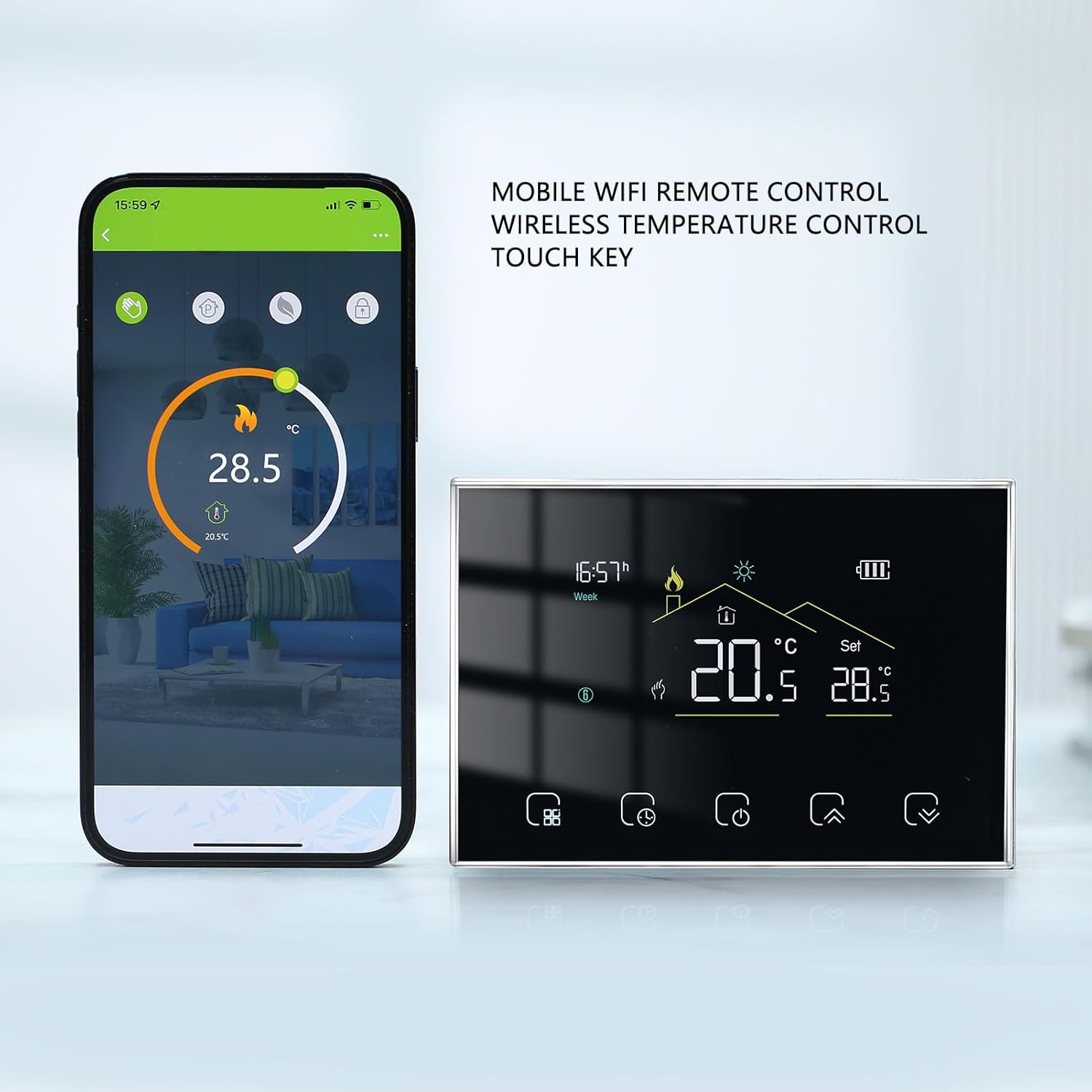
Figure 5: Mobile WiFi Remote Control. The thermostat can be managed via a smartphone application, offering wireless temperature control.
8.2 Voice Assistant Compatibility
The thermostat is compatible with popular smart speakers and voice assistants, including Tmall Genie, Yandex Alice, and Duer OS. Follow the instructions provided by your smart speaker's manufacturer to link your thermostat account and enable voice commands.
9. Maintenance
- Cleaning: Wipe the display and casing with a soft, dry cloth. Do not use abrasive cleaners, solvents, or spray directly onto the device.
- Battery Replacement: Replace AA batteries in the Display unit when the low battery indicator appears.
- Firmware Updates: Check the mobile application periodically for any available firmware updates to ensure optimal performance and access to new features.
10. Troubleshooting
| Problem | Possible Cause | Solution |
|---|---|---|
| Display is blank | Dead batteries; Power off | Replace AA batteries; Press power button |
| Heating system not responding | Receiver not powered; Wiring issue; Display/Receiver not paired | Check power to receiver; Verify wiring; Re-pair units (Section 5.4) |
| Incorrect temperature reading | Sensor interference; Temperature compensation needed | Relocate display away from drafts/heat sources; Adjust compensating temperature in settings (Function No. 4) |
| Cannot connect to Wi-Fi/App | Incorrect Wi-Fi password; Router issues; Thermostat not in pairing mode | Verify Wi-Fi password; Restart router; Follow app's pairing instructions carefully |
11. Specifications
11.1 General Specifications
| Parameter | Value |
|---|---|
| Item Type | Smart Thermostat |
| Material | ABS and PC |
| Model | BHT-8000-RF |
| Display Power Supply | 2 x AA battery (not included) |
| Receiver Power Supply | 95-240V AC |
| Sensor | 3950, 10K |
| Set Temperature Range | 5 - 35℃ |
| Accuracy | ±1℃ (Control accuracy: 0.5℃) |
| Display Temperature Range | 5 - 99℃ |
| Operating Temperature | 0 - 45℃ |
| Operating Humidity | 5 - 95% RH (non-condensing) |
| Power Consumption | <1.5W |
| Protecting Level | IP20 |
| Key Type | Capacitive touch key |
11.2 Advanced Settings Parameters
| No. | Function | Description | Default Value |
|---|---|---|---|
| 1 | Matching | 00: Stop coding; 01: Starts code alignment | 0 |
| 2 | Device ID | 0-99 | 0 |
| 3 | Code matching success | 00: Code alignment fails; 01: The code is successfully paired (Read only) | - |
| 4 | Compensating temperature | -9~9°C | -2 |
| 5 | Dead zone temperature | 1~5°C | 1 |
| 6 | Minimum temperature range | 5~15°C | 5℃ |
| 7 | Maximum temperature range | 15~35°C | 35℃ |
| 8 | Standby brightness | 0~7 | 0 |
| 9 | Energy saving mode | 00: Disables the energy saving mode. 01: enables the energy saving mode | 0 |
| 10 | Energy saving temperature | 5~30°C | 20 |
| 11 | All ICONS are displayed upon startup | 00: Close; 01: Open | 0 |
| 12 | Factory data reset | 00: Normal mode. 01: Restores the factory defaults. | 0 |
| 13 | Version number | U2 (Read only) | - |
12. Warranty and Support
Klanata products are designed for reliability and performance. For warranty information, please refer to the warranty card included with your product or visit the official Klanata website. For technical support, troubleshooting assistance, or to inquire about replacement parts, please contact Klanata customer service through the contact information provided on the official website or your purchase documentation.
Please retain your proof of purchase for warranty claims.