
1. Introduction
This manual provides essential information for the setup, operation, and maintenance of your LILYGO T-SIM7670G-S3-Standard IoT development board. The T-SIM7670G-S3-Standard integrates an ESP32-S3 microcontroller with a SIM7670G 4G LTE module, offering robust wireless connectivity for various Internet of Things applications. It supports Wi-Fi, Bluetooth 5 (LE), and 4G LTE cellular communication, along with GPS capabilities.
2. Product Overview
The LILYGO T-SIM7670G-S3-Standard is a versatile development board designed for IoT projects requiring cellular and wireless connectivity. Key components include the ESP32-S3 chip, SIM7670G module, USB-C ports, and various expansion headers.

Figure 2.1: Front view of the LILYGO T-SIM7670G-S3-Standard development board, showcasing the ESP32-S3 module, SIM7670G cellular module, USB-C ports, and various connectors.
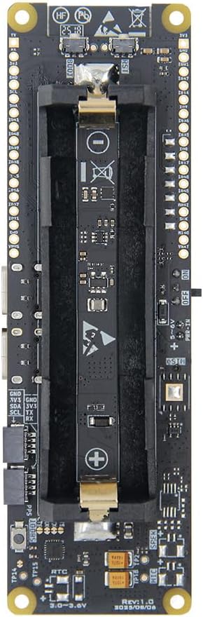
Figure 2.2: Back view of the LILYGO T-SIM7670G-S3-Standard, highlighting the integrated 18650 battery holder for portable power solutions.

Figure 2.3: Perspective view showing both the front and back sides of the LILYGO T-SIM7670G-S3-Standard board, illustrating its compact design.

Figure 2.4: Physical dimensions of the LILYGO T-SIM7670G-S3-Standard board: Length (L) 111mm, Width (W) 33mm, Height (H) 20mm.

Figure 2.5: Contents included in the LILYGO T-SIM7670G-S3-Standard package: 1x T-SIM7670G-S3-Standard board, 2x Pin headers, 1x LTE Antenna, 1x GPS Antenna, 1x Power Cable.

Figure 2.6: Dimensions of the product packaging box: Length (L) 125mm, Width (W) 52mm, Height (H) 31mm.
3. Setup
3.1. SIM Card Installation
- Locate the Nano SIM card slot on the board.
- Carefully insert a Nano SIM card into the slot, ensuring correct orientation. The SIM card should click into place.
- To remove, gently press the SIM card to release it.
3.2. Antenna Connection
- Identify the U.FL connectors for the LTE and GPS antennas.
- Connect the provided LTE antenna to the designated LTE U.FL connector.
- Connect the provided GPS antenna to the designated GPS U.FL connector.
- Ensure connections are secure but avoid excessive force.
3.3. Power Supply
- USB-C Power: Connect a USB-C cable to one of the USB-C ports on the board and to a 5V power source (e.g., computer USB port, USB power adapter).
- 18650 Battery: Insert an 18650 Li-ion battery into the battery holder on the back of the board, observing correct polarity (+/-). The board includes battery management for charging and discharge protection.
- External Power: The board supports a supply voltage of 3.4V-4.2V. Refer to the pinout diagram for external power input options.
4. Operating Instructions
4.1. Initial Power On
Once powered, the ESP32-S3 microcontroller will begin executing its programmed firmware. Status LEDs on the board may indicate power and network activity.
4.2. Software Development
- The board is compatible with the ESP-IDF (Espressif IoT Development Framework) and Arduino IDE.
- Connect the board to your computer via a USB-C cable for programming and serial communication.
- Install the necessary drivers and development environment as per Espressif documentation.
- Refer to the official LILYGO GitHub repository for example code and libraries: github.com/Xinyuan-LilyGO/LilyGO-T-A76XX.
4.3. Cellular (4G LTE) Connectivity
- Ensure a valid and activated Nano SIM card is inserted.
- The SIM7670G module will attempt to connect to the cellular network. This process may take some time.
- Use AT commands or specific libraries in your code to manage cellular functions, including data transfer, SMS (note: SMS is not supported by SIM7670G), and GPS.
4.4. Wi-Fi and Bluetooth
The ESP32-S3 supports 2.4 GHz Wi-Fi (802.11 b/g/n) and Bluetooth 5 (LE). Standard ESP-IDF or Arduino libraries can be used to implement Wi-Fi and Bluetooth functionalities.
5. Maintenance
- Cleaning: Keep the board clean and free from dust and debris. Use a soft, dry brush or compressed air for cleaning. Avoid liquid cleaners.
- Storage: Store the board in a dry, anti-static environment when not in use.
- Handling: Handle the board by its edges to avoid touching sensitive components. Electrostatic discharge can damage electronic components.
- Battery Care: If using an 18650 battery, ensure it is in good condition. Do not expose batteries to extreme temperatures or physical damage.
6. Troubleshooting
- Board Not Powering On:
- Check USB-C cable connection and power source.
- Ensure 18650 battery is correctly inserted and charged if used.
- No Cellular Network Connection:
- Verify SIM card is active and has a data plan.
- Ensure LTE antenna is securely connected.
- Check network coverage in your area.
- Confirm correct APN settings in your code.
- Wi-Fi/Bluetooth Issues:
- Verify Wi-Fi/Bluetooth code implementation.
- Check for interference from other 2.4 GHz devices.
- Programming Errors:
- Ensure correct board selection and port in your IDE.
- Install all required drivers and libraries.
- Consult Espressif and LILYGO documentation for specific programming guidance.
7. Specifications
Below are the detailed technical specifications for the LILYGO T-SIM7670G-S3-Standard.

Figure 7.1: Core specifications including MCU, LTE/GSM module, TF Card support, ESP32-S3 clock speed, flash, PSRAM, wireless connectivity, and peripheral interfaces.

Figure 7.2: Connectivity and power specifications, detailing LTE frequency bands, data transfer speeds, GNSS support, communication protocols, USB driver compatibility, supply voltage, SIM card type, and certifications.
7.1. Pinout Diagrams
Understanding the pinout is crucial for connecting external components and sensors.

Figure 7.3: Pinout diagram for the LILYGO T-SIM7670G-S3 Cat1 variant, showing GPIO assignments and peripheral connections.

Figure 7.4: Pinout diagram for the LILYGO T-SIM7670G-S3-Standard, detailing GPIOs, power pins, and module-specific connections, including camera pin (optional) and SIM card/TF card slots.
8. Warranty Information
Specific warranty details for the LILYGO T-SIM7670G-S3-Standard are not provided in this manual. Please refer to the product's purchase documentation or contact LILYGO customer support for warranty terms and conditions.
9. Support
For further assistance, technical documentation, and community support, please refer to the following resources:
- Official GitHub Repository: github.com/Xinyuan-LilyGO/LilyGO-T-A76XX
- Model Comparison: For distinctions between T-SIM7670G-S3-Standard and T-SIM7670G-S3, refer to: github.com/Xinyuan-LilyGO/LilyGo-Modem-Series/blob/main/docs/model_comparison.md
- Customer Support: If you have any questions or suggestions about the product, please feel free to contact LILYGO customer service.