
Introduction
This manual provides essential information for the installation, operation, and maintenance of the US Automatic 500016 Main Logic Control Board. This board is a direct replacement for older models 500001 and 500002, designed for use with Pre-2016 US Automatic Patriot Slide and Swing Gate Openers. It is compatible with both AC power and solar power applications, ensuring versatile use.
The 500016 control board is an OEM Genuine US Automatic component, ensuring compatibility and reliable performance with your existing gate opener system.
Safety Information
Warning: Installation and servicing of this control board should only be performed by qualified personnel. Improper installation or handling of electrical components can result in serious injury or damage to the equipment.
- Always disconnect power to the gate opener system before performing any installation, maintenance, or troubleshooting.
- Ensure all wiring connections are secure and comply with local electrical codes.
- Keep hands and loose clothing clear of moving gate parts during operation.
- Do not allow children to operate or play near the gate opener system.
Package Contents
- 1 x US Automatic 500016 Main Logic Control Board
Setup and Installation
The 500016 control board is designed for straightforward replacement of older 500001 and 500002 models. Carefully observe the existing wiring configuration before removal.
Board Layout Overview
Familiarize yourself with the layout of the control board. The board features various terminals for power, accessories, and safety devices, along with DIP switches and potentiometers for configuration.
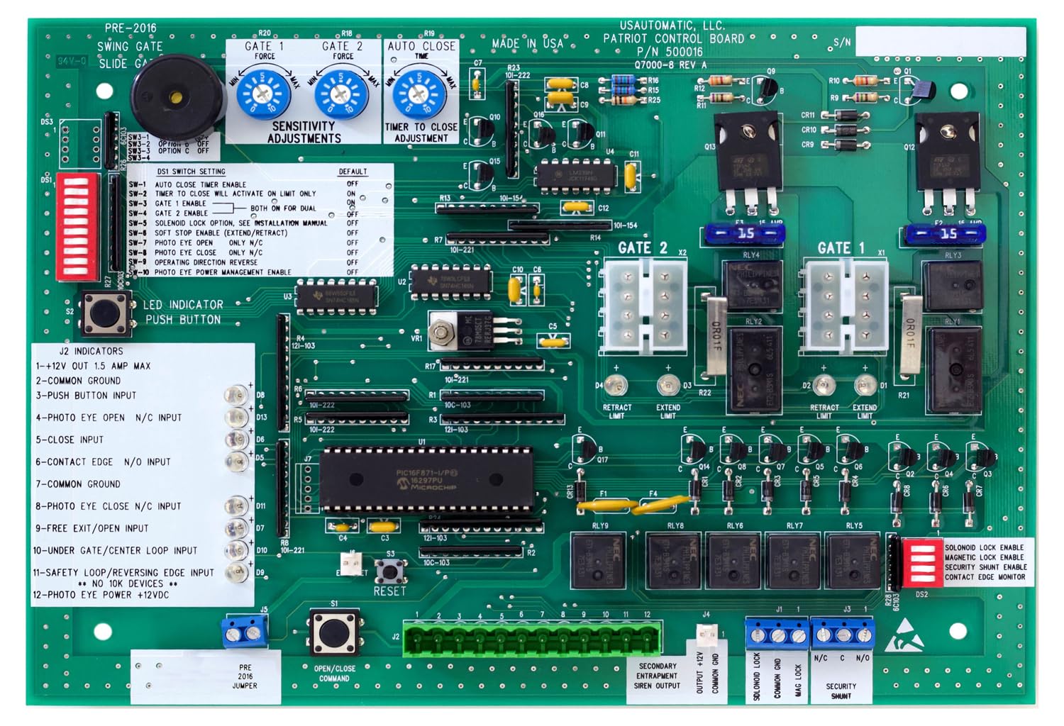
Figure 1: US Automatic 500016 Main Logic Control Board. This image displays the primary layout of the 500016 board, showing DIP switches, J2 indicators, and adjustment potentiometers for force, sensitivity, and auto-close timer.

Figure 2: Older US Automatic 500002 Main Logic Control Board. This image shows the layout of the older 500002 board, which the 500016 replaces. Note the similarities and differences in component placement.
Replacement Procedure
- Disconnect Power: Ensure all power to the gate opener system is completely disconnected at the main breaker.
- Document Wiring: Take clear photos or make detailed diagrams of all existing wiring connections to the old control board. Pay close attention to terminal labels.
- Remove Old Board: Carefully disconnect all wires and mounting screws holding the old control board in place.
- Install New Board: Mount the new 500016 control board in the same location.
- Reconnect Wiring: Reconnect all wires to the corresponding terminals on the new 500016 board, referring to your documentation. Ensure all connections are tight and secure.
- Initial Configuration: Set the DIP switches and potentiometers according to your gate opener model and desired operation. Refer to the 'Operating Instructions' section for details.
- Restore Power: Once all connections are verified, restore power to the gate opener system.
- Test Operation: Perform several test cycles to ensure the gate operates correctly and all safety features are functional.
Operating Instructions
The 500016 control board features adjustable settings via DIP switches and potentiometers to customize gate operation.
DIP Switch Settings (Refer to Figure 1)
The DIP switches control various operational parameters. Set them according to your specific gate opener model and desired functionality.
- SW-1 Auto Close Timer Enable: ON enables the auto-close timer.
- SW-2 Timer to Close Will Activate on Limit Only: ON means the timer starts only after the gate reaches its fully open or closed limit.
- SW-3 Gate 1 Enable: ON enables Gate 1 operation.
- SW-4 Gate 2 Enable: ON enables Gate 2 operation.
- SW-5 Solenoid Lock Option: Refer to the specific solenoid lock manual for settings.
- SW-6 Soft Stop Retract Enable: ON enables soft stop functionality during retraction.
- SW-7 Soft Stop Extend Enable: ON enables soft stop functionality during extension.
- SW-8 Stop Circuit Enable: ON enables the stop input.
- SW-9 Operating Direction Reverse: ON reverses the gate's operating direction.
- SW-10 Photo Eye Power Management Enable: ON enables power management for photo eyes.
Potentiometer Adjustments (Refer to Figure 1)
- R20 Gate 1 Force: Adjusts the force applied by Gate 1.
- R18 Gate 2 Force: Adjusts the force applied by Gate 2.
- R19 Auto Close Timer: Adjusts the delay before the gate automatically closes (if enabled by DIP switch).
- R17 Current Sense Adjustment: Adjusts the sensitivity of the current sensing for obstruction detection.
J2 Indicators (Refer to Figure 1)
The J2 indicators provide visual feedback on the board's status and inputs:
- 1 - +12V OUT 1.5 AMP MAX: +12V power output.
- 2 - COMMON GROUND: Common ground connection.
- 3 - PUSH BUTTON INPUT: Input for external push button control.
- 4 - OPEN SAFETY EDGE: Input for open safety edge.
- 5 - CLOSE INPUT: Input for close command.
- 6 - CONTACT EDGE 2ND ENTRAPMENT INPUT: Input for a second entrapment contact edge.
- 7 - COMMON GROUND: Additional common ground.
- 8 - STOP CIRCUIT INPUT N/C: Normally closed stop circuit input.
- 9 - FREE EXIT/OPEN INPUT: Input for free exit or open command.
- 10 - UNDER GATE/CENTER LOOP INPUT: Input for under gate or center loop detector.
- 11 - SAFETY LOOP/REVERSING EDGE INPUT: Input for safety loop or reversing edge.
- 12 - MOTION DETECTOR INPUT: Input for motion detector.
Maintenance
The US Automatic 500016 control board requires minimal maintenance. Regular inspection of the gate opener system is recommended.
- Periodically inspect all wiring connections to ensure they remain secure and free from corrosion.
- Keep the control board enclosure clean and free of dust, debris, and insects.
- Check for any signs of physical damage to the board or its components.
Troubleshooting
If your gate opener system is not functioning as expected, perform the following basic troubleshooting steps:
- No Power: Check the main power supply to the gate opener and ensure the circuit breaker is not tripped. Verify all power connections to the control board.
- Gate Not Responding: Check the status of the J2 indicators for any fault signals. Verify that all safety devices (photo eyes, safety edges) are clear and properly connected. Ensure DIP switch settings are correct for your configuration.
- Intermittent Operation: Inspect all wiring for loose connections or damaged insulation. Check for environmental factors affecting sensors or limits.
- Gate Not Closing/Opening Fully: Adjust the force and limit switch settings. Ensure no physical obstructions are impeding gate movement.
For complex issues, consult a qualified gate opener technician or contact US Automatic customer support.
Specifications
| Manufacturer | US Automatic |
| Product Dimensions | 8 x 5 x 1 inches |
| Item Model Number | 500016 (Replaces 500001 / 500002) |
| Included Components | Control Board |
| Compatibility | Pre-2016 US Automatic Slide and Swing Gate Openers |
| Power Applications | AC Power and Solar Power |
| Date First Available | January 18, 2026 |
Warranty and Support
This US Automatic 500016 Main Logic Control Board is covered by the manufacturer's standard warranty. Please refer to the warranty documentation provided with your original gate opener system or contact US Automatic directly for specific warranty terms and conditions.
For technical assistance, troubleshooting, or to inquire about replacement parts, please contact US Automatic customer support. Contact information can typically be found on the manufacturer's website or in your original product documentation.


