1. Introduction
This manual provides essential information for the safe and efficient operation of your DATOUBOSS 12V 1800W Hybrid Solar Inverter. This device integrates a solar charge controller, an inverter, and a battery charger into one unit, offering a comprehensive solution for off-grid and hybrid power systems. It is designed to convert 12V DC power to 230V AC pure sine wave power, suitable for various household and office appliances.
Please read this manual thoroughly before installation and use, and retain it for future reference.
2. Safety Instructions
Observe the following safety precautions during installation, operation, and maintenance:
- Installation must be performed by qualified personnel.
- Ensure all wiring is correctly connected and securely fastened to prevent loose connections that can cause overheating.
- Do not expose the inverter to rain, snow, spray, or any liquids.
- Do not disassemble the unit. There are no user-serviceable parts inside.
- Ensure adequate ventilation around the inverter to prevent overheating.
- Wear appropriate personal protective equipment (PPE) during installation and maintenance.
- Disconnect all power sources (solar, battery, AC grid) before performing any maintenance or wiring.
- This inverter is designed for indoor use or in a protected environment.
3. Product Overview
The DATOUBOSS Hybrid Solar Inverter combines three functions in one unit: a solar inverter, a battery charger, and an MPPT charge controller. This design simplifies cabling and optimizes space utilization.
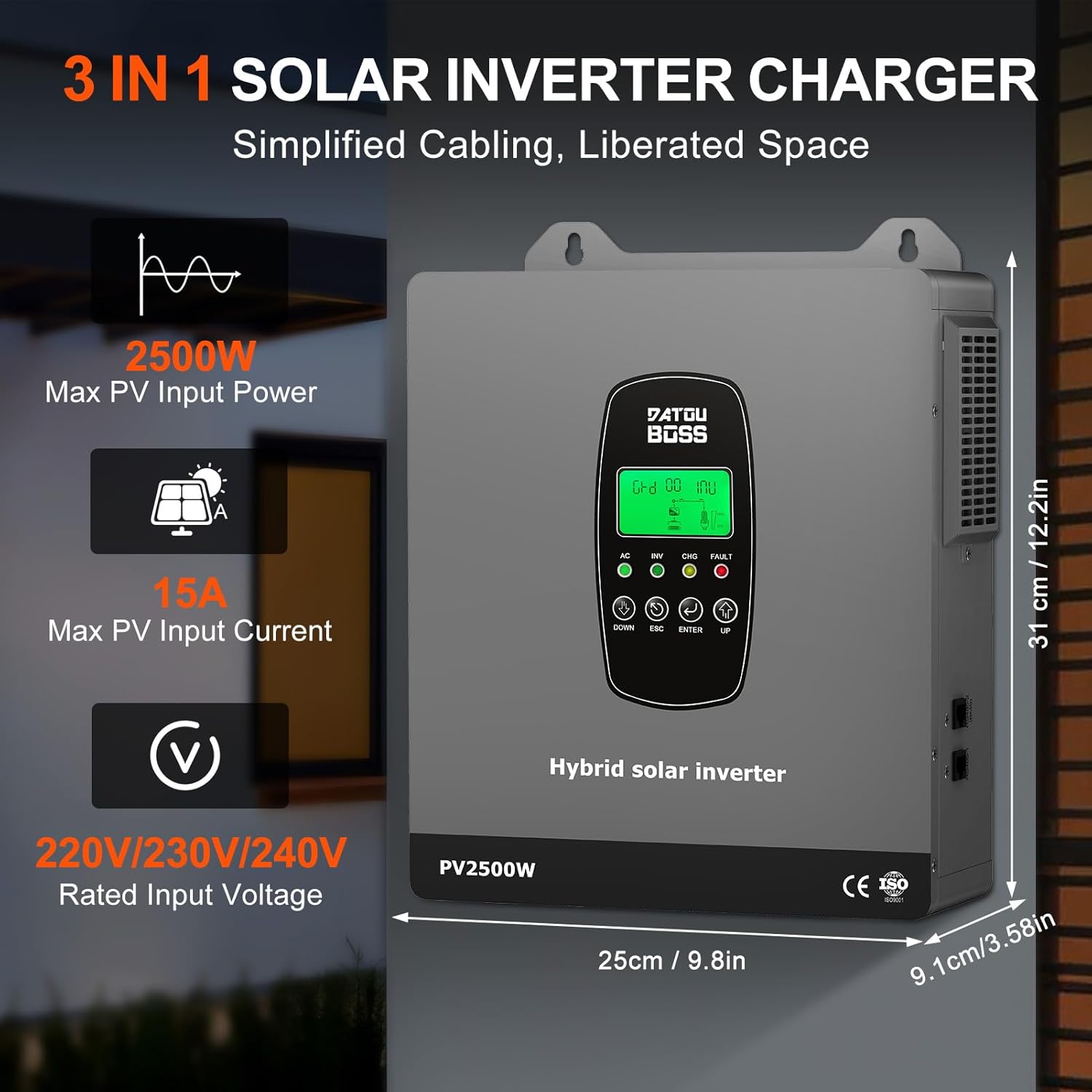
Figure 3.1: Front view of the DATOUBOSS Hybrid Solar Inverter showing key features and dimensions. The inverter has a maximum PV input power of 2500W, maximum PV input current of 15A, and a rated input voltage of 220V/230V/240V. Dimensions are approximately 31 cm (12.2 in) height, 25 cm (9.8 in) width, and 9.1 cm (3.58 in) depth.
3.1 Component Identification

Figure 3.2: Detailed view of the inverter's interfaces. The front panel features an LCD display and function key control area. The right side includes an RS485-2 communication interface (BMS communication). The left side has a power on/off switch and an RS485-1 communication interface (External communication/WIFI). The bottom interface includes AC input (on-grid) terminal, Earth wire, AC output, Fan, Battery terminal port, and PV input terminal port.
4. Setup and Installation
The inverter is designed for wall-mounted installation. Ensure the mounting surface is strong enough to support the unit's weight and that there is sufficient clearance for ventilation.
4.1 Wiring Diagram
Follow the wiring diagram carefully. All connections must be secure and correctly polarized.

Figure 4.1: Wiring diagram illustrating connections for the solar system, power grid, 12V battery, and AC output. The solar input connects to the PV input terminal, the grid connects to the AC input terminal, the 12V battery connects to the battery terminal, and loads connect to the AC output terminal.

Figure 4.2: Comprehensive wiring and technical specifications diagram. This image details the connections for the solar system (Max PV Input Power 2500W, MPPT Tracking Range 30-240VDC), power grid (Rated Voltage 220V/230V/240V), 12V battery (Lead-acid/Lithium, Max PV Charging Current 100A), and AC output (Rated Output Power 1800W, Pure Sine Wave).
4.2 Connection Steps
- Mounting: Securely mount the inverter to a vertical surface using appropriate fasteners.
- Battery Connection: Connect the 12V battery bank to the battery terminals. Ensure correct polarity (positive to positive, negative to negative).
- Solar Panel Connection: Connect the solar panel array to the PV input terminals. Observe correct polarity and ensure the PV open circuit voltage is within the specified range.
- AC Input (Grid) Connection: If connecting to the utility grid, connect the AC input from the grid to the designated AC input terminals.
- AC Output (Load) Connection: Connect your AC loads to the AC output terminals.
- Grounding: Connect the inverter to an earth ground using the designated earth wire terminal.
- Power On: After verifying all connections, switch on the power.
5. Operating Instructions
The inverter features an LCD display and control buttons for configuration and monitoring.
5.1 LCD Display and Control
The LCD displays real-time system status, including voltage, power, battery status, and operational mode. Error codes are displayed for quick troubleshooting.
5.2 Charging Modes
The inverter offers versatile charging and output modes to suit different energy management needs:

Figure 5.1: Illustration of the four charging modes and three charge output working modes. Charging modes include AC priority, Solar priority, Mixed loading (Solar and mains), and Solar only. Output modes include Solar priority, Utility priority, and SBU mode (Solar-Battery-Utility).
- Four Charging Modes:
- AC Priority: If no mains power is available, the battery is charged using solar energy.
- Solar Priority: Charging with solar energy priority. If no solar power is available, the battery is charged via the power grid.
- Mixed Loading: Solar and mains power can charge the battery at the same time.
- Solar Only: The battery can only be charged using solar energy.
- Three Configurable Output Modes:
- PV Priority: Prioritizes power from solar panels.
- Grid Priority: Prioritizes power from the utility grid.
- Hybrid Inverter Priority (SBU Mode): Prioritizes solar, then battery, then utility.
6. Battery Compatibility
The inverter is compatible with various 12V battery types, including lead-acid (sealed, AGM, gel, flooded) and lithium batteries. It features a built-in Battery Management System (BMS) to prevent overcharging and deep discharging, extending battery life.

Figure 6.1: The inverter supports various battery types including GSL (Gel Sealed Lead-Acid), LN (Lithium-ion), FLB (Flooded Lead-Acid), LI (LiFePO4), SLA (Sealed Lead-Acid), and USER-defined. Users can configure the battery type via the LCD display. The maximum battery charging current is 100A.
7. Monitoring
The inverter provides real-time monitoring capabilities through its integrated LCD display and optional WiFi module.
7.1 WiFi Monitoring
With the optional WiFi module, users can monitor the inverter's performance in real-time via a web interface or a dedicated mobile application, eliminating the need to check the controller's LCD directly.

Figure 7.1: The inverter is WiFi monitoring ready, allowing users to view system performance remotely via a web browser or mobile app.
8. Protection Functions
The DATOUBOSS Hybrid Solar Inverter incorporates multiple protection features to ensure safe and reliable operation of your power system.

Figure 8.1: The inverter provides comprehensive protection against overload, short circuit, and surge hazards. Specific protections include reverse connection protection, short circuit protection, high temperature protection, overload protection, overcurrent protection, and over-discharge protection.

Figure 8.2: This diagram highlights the inverter's multiple protection features, including overvoltage protection, short circuit protection, overcharge protection, over-discharge protection, temperature protection, undervoltage protection, overload protection, and overcurrent protection.
9. Specifications
Detailed technical specifications for the DATOUBOSS 12V 1800W Hybrid Solar Inverter (Model: DT-1218M-A-EU).

Figure 9.1: Detailed technical parameters including Product Name: Solar Inverter, Model: DT-1218M, Protection Degree: IP20, Rated Power: 1800W. Battery parameters: DC Input 12VDC, Max. AC Charging Current 65A, Max. PV Charging Current 100A, Max. Charging Current 100A. PV Input parameters: Max. PV Input Power 2500W, Max. PV Input Voltage (Voc) 300VDC, Max. PV Input Current 15A, MPPT Tracking Range 30-240VDC, Rated PV Input Voltage 180VDC, Number of MPPT: 1.

Figure 9.2: Technical specifications for Model DT-1218M. Includes PV input (Max PV Power 2500W, MPPT Tracking Range 30-240VDC), Battery & Charging (Type: Custom, 12VDC, Max PV Charging Current 100A), Hybrid Operation (Rated Input Voltage 220V/230V/240V, Rated Output Power 1800W, Pure Sine Wave), AC Input/Output, Regular Parameters (Max Conversion Efficiency 94%, MPPT Tracking Efficiency >99.9%), Environment (Operating Temp -10°C to 50°C), Dimension and Weight (Product Size 310x250x91mm, N.W. 4.0kg), and Protection features.

Figure 9.3: Continuation of technical specifications, detailing On-Grid Operation (Rated Output Power 1800W, 220V/230V/240VAC), Off-Grid Operation (Rated Input Voltage 220V/230V/240V, Rated Output Power 1800W, Pure Sine Wave), and environmental conditions.
| Parameter | Value |
|---|---|
| Brand | DATOUBOSS |
| Model Number | DT-1218M-A-EU |
| Rated Power | 1800 Watts |
| Voltage | 12 Volts |
| Max PV Input Power | 2500W |
| Max PV Input Voltage (Voc) | 300V DC |
| MPPT Tracking Range | 30-240V DC |
| Max PV Input Current | 15A |
| Max Hybrid Charging Current | 100A |
| AC Output Voltage | 220V/230V/240V AC |
| AC Output Frequency | 50/60Hz |
| Output Waveform | Pure Sine Wave |
| Battery Compatibility | 12V Lead-acid (sealed, AGM, gel, flooded), Lithium |
| Protection Degree | IP20 |
| Operating Temperature | -10°C to 50°C |
| Dimensions (L*W*H) | 310 x 250 x 91 mm |
| Net Weight | 4.0 kg |
10. Troubleshooting
This section provides guidance for common issues. The LCD display will show error codes to assist in diagnosis.
| Error Code / Symptom | Possible Cause | Solution |
|---|---|---|
| Overload Alarm | Connected load exceeds inverter's rated power. | Reduce the connected load. Check appliance power ratings. |
| Short Circuit | Short circuit detected at AC output. | Disconnect all loads and check wiring for shorts. |
| High Temperature | Inverter is overheating due to poor ventilation or excessive load. | Ensure adequate airflow around the unit. Reduce load if necessary. Check fan operation. |
| Battery Low Voltage | Battery voltage is below the acceptable threshold. | Charge the battery. Check battery connections and health. |
| PV Overvoltage | Solar panel input voltage exceeds maximum limit. | Verify solar panel configuration and ensure Voc is within range. |
If the issue persists after attempting these solutions, please contact customer support.
11. Maintenance
Regular maintenance ensures optimal performance and longevity of your inverter.
- Cleaning: Periodically clean the exterior of the inverter with a dry cloth. Ensure ventilation openings are free from dust and debris.
- Connection Checks: Annually inspect all wiring connections (battery, solar, AC input/output) for tightness and corrosion. Tighten any loose connections.
- Battery Inspection: Regularly check the battery terminals for corrosion and ensure they are clean and tight. For flooded lead-acid batteries, check electrolyte levels and top up with distilled water if necessary.
- Environmental Check: Ensure the installation environment remains within specified temperature and humidity ranges.
12. Warranty and Support
The DATOUBOSS 12V 1800W Hybrid Solar Inverter comes with a 2-year manufacturer warranty.
For technical support, warranty claims, or service inquiries, please contact your retailer or DATOUBOSS customer service. Provide your product model number (DT-1218M-A-EU) and serial number (if applicable, e.g., S/N:86HFP1800250627507500-405) when contacting support.