
1. Introduction
This manual provides essential information for the safe and effective operation of your GenSDH GCS909-3 Digital Readout (DRO) Display. The GCS909-3 is a versatile 3-axis DRO system designed for milling and lathe applications, supporting TTL linear scales. It features a multi-language interface and is compatible with AC110V/220V power supplies.
Please read this manual thoroughly before installation and operation to ensure proper use and to prevent damage to the device or injury to personnel.
2. Safety Information
- Ensure the power supply voltage matches the device's requirements (AC110V/220V).
- Do not open the device casing. Refer all servicing to qualified personnel.
- Avoid exposing the device to excessive moisture, dust, or extreme temperatures.
- Disconnect power before performing any installation, maintenance, or cleaning procedures.
- Use only specified accessories and linear scales with the DRO.
3. Product Overview
The GenSDH GCS909-3 Digital Readout Display is designed for precision measurement in machining operations. Key features include:
- 3-Axis Support: Simultaneous display for X, Y, and Z axes.
- Multi-Language Interface: Supports 19 different languages for user convenience.
- Wide Resolution Range: Acceptable resolution from 0.1µm to 20µm.
- TTL Input Signal: Compatible with standard TTL linear scales.
- Universal Power Supply: Operates on 80-250V, 50Hz-60Hz AC power.
- DB9 Connector: Standard connector type for linear scale input.
3.1 Rear Panel Connections
The rear panel of the GCS909-3 features all necessary input and output ports, including power input and DB9 connectors for linear scales.
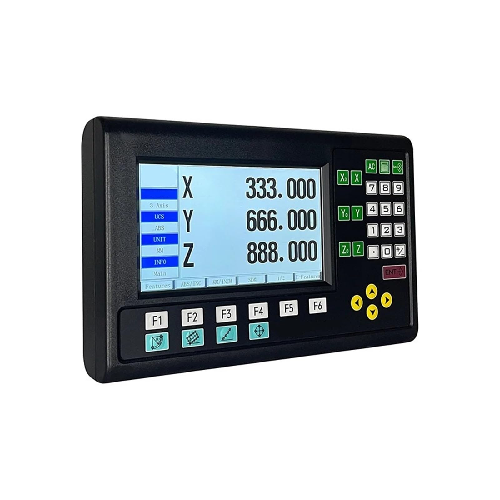
Figure 1: Rear panel of the GCS909-3 DRO, illustrating the power switch, AC power inlet, and three DB9 ports labeled X, Y, and Z for linear scale connections.
3.2 DB9 Connector Details
The GCS909-3 uses standard DB9 connectors for connecting TTL linear scales. Ensure correct pin assignments during connection.

Figure 2: A close-up image of a DB9 connector, showing the nine pins arranged in two rows.
3.3 DB9 TTL Signal Connection Method
The following table details the pin assignments for TTL signal input via the DB9 connector:

Figure 3: DB9 connection method for TTL signals, indicating the function of each pin. Pin 1: +5V, Pin 2: 0V, Pin 3: A, Pin 4: B, Pin 5: R. Pins 6-9 are not used.
4. Setup
4.1 Mounting the DRO
The GCS909-3 features a compact design for easy integration. Securely mount the DRO display in a location that provides clear visibility and easy access to controls, away from excessive vibration or heat sources. Use appropriate fasteners for your mounting surface.
4.2 Connecting Linear Scales
- Identify the X, Y, and Z axis DB9 connectors on the rear panel of the DRO.
- Connect your TTL linear scales to the corresponding DB9 ports. Ensure the connectors are fully seated and secured. Refer to Figure 3 for correct pin assignments if custom wiring is required.
- Verify that the linear scales are securely mounted to your machine tool and aligned correctly to ensure accurate displacement readings.
4.3 Power Connection
- Ensure the power switch on the rear panel is in the OFF position.
- Connect the provided power cable to the AC power inlet on the rear panel (refer to Figure 1).
- Plug the other end of the power cable into a grounded AC outlet (80-250V, 50Hz-60Hz).
5. Operating Instructions
5.1 Powering On/Off
- To power on, flip the power switch on the rear panel to the ON position. The display will illuminate.
- To power off, flip the power switch to the OFF position.
5.2 Language Selection
Upon initial power-up or through the system settings menu, you can select from 19 available languages. Consult the on-screen prompts or the dedicated language setting section within the DRO's menu for detailed instructions on changing the display language.
5.3 Basic Measurement Functions
The GCS909-3 displays real-time displacement values for each connected axis (X, Y, Z). Common functions include:
- Zero Set: Resets the current axis reading to zero.
- Absolute/Incremental Mode: Toggles between absolute (ABS) and incremental (INC) measurement modes.
- Half Function: Divides the current reading by two, useful for finding center points.
- Axis Switching: Selects which axis's specific functions or settings are being adjusted.
5.4 Resolution Setting
The acceptable resolution can be set from 0.1µm to 20µm. Access the resolution settings through the DRO's menu to match the precision requirements of your application and the specifications of your linear scales.
5.5 Advanced Functions (Programming)
The GCS909-3 includes full functionality for fast programming, which may include features such as:
- Hole pattern calculations (PCD, Line of Holes).
- Arc processing.
- Tool compensation.
- Taper measurement.
Refer to the on-screen menu and specific function guides within the DRO for detailed instructions on utilizing these advanced programming features.
6. Maintenance
6.1 Cleaning
- Ensure the DRO is powered off and disconnected from the power supply before cleaning.
- Wipe the display and casing with a soft, dry, or slightly damp cloth.
- Do not use abrasive cleaners, solvents, or harsh chemicals, as these can damage the display or casing.
6.2 Environmental Considerations
- Operate the DRO within its specified temperature and humidity ranges.
- Protect the device from direct sunlight and excessive heat.
- Keep the device free from metal chips, coolant, and other debris common in machining environments.
7. Troubleshooting
| Problem | Possible Cause | Solution |
|---|---|---|
| Display does not power on. | No power supply; Power cable loose; Power switch off. | Check power outlet; Ensure power cable is securely connected; Turn power switch ON. |
| No reading from an axis. | Linear scale not connected; Damaged scale cable; Faulty scale. | Verify scale connection to the correct DB9 port; Inspect cable for damage; Test with a known working scale. |
| Inaccurate readings. | Scale misalignment; Incorrect resolution setting; Debris on scale. | Check and adjust scale alignment; Verify resolution setting in menu; Clean linear scale surface. |
| Display shows error code. | Internal fault; Communication error. | Note the error code and consult the manufacturer for specific guidance. Try restarting the device. |
8. Specifications
| Feature | Specification |
|---|---|
| Model Number | GCS909-3 |
| Languages Supported | 19 |
| Axis Support | 3-Axis (X, Y, Z) |
| Acceptable Resolution | 0.1µm - 20µm |
| Input Signal Type | TTL |
| DRO Power Supply | 80-250V AC, 50Hz-60Hz |
| Connector Type (for Scale) | DB9 |
| Scale Output Voltage | 5V |
| Manufacturer | GenSDH |
9. Warranty Information
This product is covered by a standard manufacturer's warranty. For specific warranty terms, duration, and conditions, please refer to the warranty card included with your product or contact the seller/manufacturer directly. Keep your proof of purchase for warranty claims.
10. Customer Support
If you encounter any issues not covered in this manual or require technical assistance, please contact your retailer or the manufacturer, GenSDH, for support. Provide your product model number (GCS909-3) and a detailed description of the problem when seeking assistance.
For the most up-to-date contact information, please refer to the official GenSDH website or the contact details provided with your purchase.