
1. Introduction
This manual provides detailed instructions for the installation, operation, and maintenance of your MUSETEX Y6 ATX Mid Tower PC Case. The Y6 case is designed for optimal airflow and component visibility, featuring a dual-chamber layout and tempered glass panels. Please read this manual thoroughly before beginning assembly to ensure proper setup and safe operation.

Image: An example build within the MUSETEX Y6 PC Case, showcasing internal components and the tempered glass panels.
2. Safety Information
- Always disconnect the power supply from the wall outlet before installing or servicing any components inside the PC case.
- Handle tempered glass panels with care. They are fragile and can break if dropped or subjected to impact.
- Be aware of sharp edges inside the case during installation. It is recommended to wear protective gloves.
- Ensure all cables are routed properly and do not obstruct fan blades or airflow.
- Do not operate the PC case in environments with excessive dust, moisture, or extreme temperatures.
3. Package Contents
Verify that all items listed below are included in your package:
- MUSETEX Y6 PC Case x1
- 120mm Non-LED Fans x4 (3 reverse fans on the side, 1 forward fan on the back)
- Instruction Manual x1
- Screw Accessory Kit x1 (includes various screws, Velcro ties, and plastic cable ties)
Note: Motherboard, graphics card, power supply, and radiator are not included.

Image: The MUSETEX Y6 PC Case shown with its four pre-installed 120mm non-LED fans, indicating their direction (forward and reverse).
4. Specifications
| Feature | Specification |
|---|---|
| Model Name | Y6 |
| Case Type | Mid Tower |
| Dimensions (D x W x H) | 16.73"D x 10.83"W x 15.67"H (425mm x 275mm x 398mm) |
| Material | Metal, Plastic, Tempered Glass |
| Motherboard Compatibility | ATX, Micro-ATX, Mini-ITX |
| CPU Cooler Height (Max) | 160mm (6.3") |
| GPU Length (Max) | 410mm (16.14") |
| PSU Length (Max) | 230mm (9.05") |
| PCI-E Slots | 7 |
| Drive Bays | 1x HDD, 2x SSD |
| Pre-installed Fans | 4x 120mm Non-LED (3 side intake, 1 rear exhaust) |
| Front I/O Ports | 1x Type-C, 1x USB 3.0, 1x USB 2.0, Microphone & Audio, Power Button, Reset Button |
| Cooling Method | Air, Water |
| Special Features | Built-In Fans, Dust Filters, Type-C Port, 270° Tempered Glass |
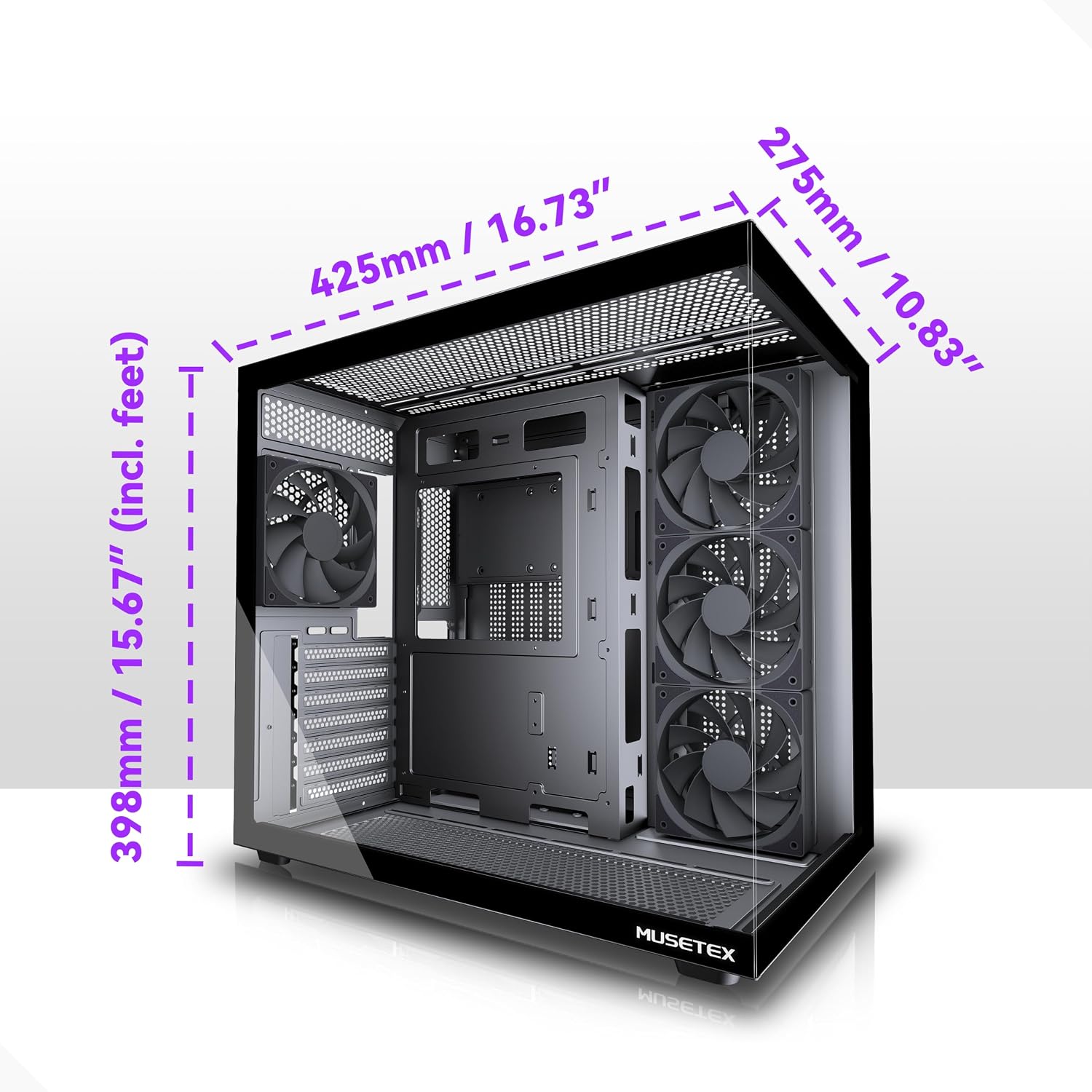
Image: A diagram illustrating the external dimensions of the MUSETEX Y6 PC Case.
5. Setup Guide
5.1 Preparation
Before starting the assembly, ensure you have the following tools:
- Phillips head screwdriver
- Anti-static wrist strap (recommended)
- Flashlight (optional, for dark areas)
5.2 Side Panel Removal
The MUSETEX Y6 case features tool-less side panels. Gently pull the tempered glass side panel outwards from the top or bottom edge to detach it. Repeat for the metal side panel on the opposite side. Store the panels safely to prevent damage.
5.3 Motherboard Installation
The Y6 case supports ATX, Micro-ATX, and Mini-ITX motherboards. Install the I/O shield into the rear opening of the case. Align your motherboard with the pre-installed standoffs and secure it with the provided motherboard screws from the accessory kit.

Image: An internal view of the case highlighting the compatible motherboard sizes: ITX, M-ATX, and ATX.
5.4 Power Supply (PSU) Installation
The power supply mounts in the dedicated compartment at the rear of the case. Slide the PSU into its bay and secure it with screws from the accessory kit. The case supports PSUs up to 230mm (9.05") in length.

Image: A diagram indicating the maximum power supply unit length supported within the case.
5.5 Storage Drive Installation
The case provides bays for 1x HDD and 2x SSDs. Install your 3.5-inch HDDs and 2.5-inch SSDs into the designated mounting locations, typically found behind the motherboard tray or in the PSU shroud area. Secure them with the appropriate screws.
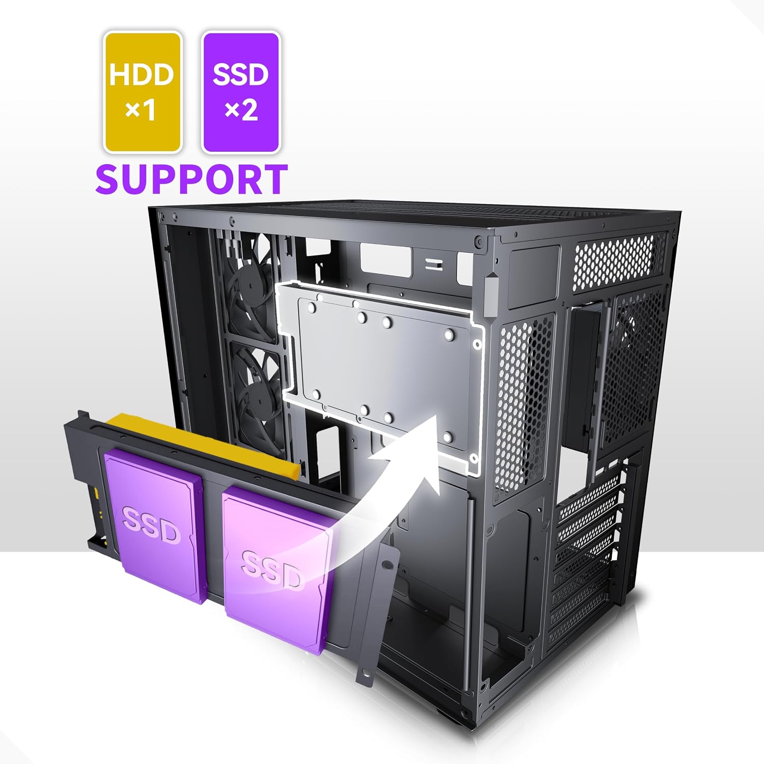
Image: A visual guide demonstrating the installation process for HDD and SSD storage drives.
5.6 Graphics Card (GPU) Installation
Remove the necessary PCI-E slot covers from the rear of the case. Insert your graphics card into the appropriate PCI-E slot on the motherboard and secure it with the provided screws. The case supports GPUs up to 410mm (16.14") in length.
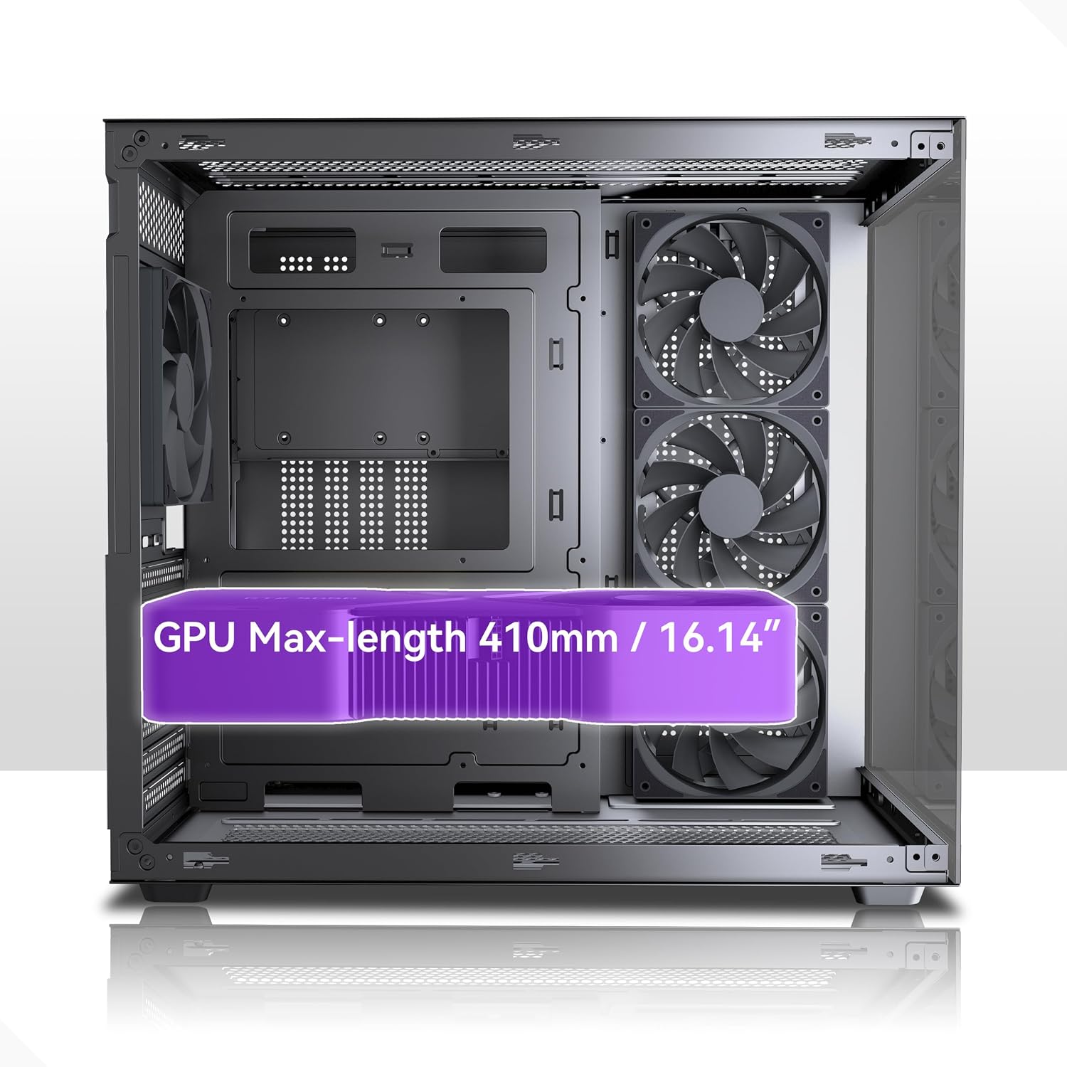
Image: A diagram illustrating the maximum graphics card length supported by the case.

Image: An internal view highlighting the 7 PCI-E slots available for expansion cards.
5.7 Fan and Radiator Installation
The Y6 case comes with four pre-installed 120mm non-LED fans (three side intake, one rear exhaust). Additional fan and radiator support is available:
- Top: Up to 3x 120mm fans or 2x 140mm fans; Radiator up to 360mm/280mm/240mm (Max thickness 60mm / 2.36")
- Side: Up to 3x 120mm fans; Radiator up to 240mm (Max thickness 65mm / 2.56")
- Bottom: Up to 3x 120mm fans; Radiator up to 360mm/240mm
- Rear: 1x 120mm fan
Ensure proper airflow direction for optimal cooling. The case features a dual-chamber design for improved thermal performance, with an independent ventilation channel for the power supply.

Image: A diagram showing the detailed and optimal airflow channel design, with arrows indicating air movement.

Image: A diagram detailing the maximum CPU cooler height and various fan and radiator mounting options.

Image: A diagram indicating the maximum radiator thickness for both top and side mounting positions.

Image: Detailed specifications for the 120mm black PC case fan, including bearing type, RPM range, airflow, noise level, and static pressure.
5.8 Cable Management
Utilize the wide channels and tie-down points behind the motherboard tray to route and conceal cables. Use the included Velcro ties and plastic cable ties to organize cables, ensuring they do not impede airflow or interfere with component installation.

Image: A diagram illustrating recommended cable routing paths for efficient cable management within the case.
5.9 Front I/O Panel Connections
Connect the front I/O panel cables to the corresponding headers on your motherboard. The front panel includes:
- 1x Type-C port
- 1x USB 3.0 port
- 1x USB 2.0 port
- Microphone & Audio jack
- Power Button
- Reset Button

Image: A close-up view of the front I/O panel, labeling the Power button, Reset button, Combo Audio jack, USB 2.0 port, USB 3.0 port, and Type-C port.
6. Operating Instructions
After completing the assembly and connecting all necessary peripherals, press the Power Button on the front I/O panel to turn on your computer. To shut down, use the operating system's shutdown procedure. The Reset Button can be used for a hard reboot if the system becomes unresponsive.
7. Maintenance
Regular maintenance helps ensure optimal performance and longevity of your PC components.
7.1 Dust Filters
The top and bottom of the case are equipped with magnetic dust filters. Periodically remove and clean these filters to prevent dust buildup inside the case, which can hinder airflow and component cooling.
7.2 General Cleaning
Use a soft, dry cloth to clean the exterior surfaces of the case, including the tempered glass panels. For internal cleaning, use compressed air to remove dust from fans and heatsinks. Ensure the system is powered off and unplugged before cleaning.
8. Troubleshooting
If you encounter issues with your PC build, consider the following general troubleshooting steps:
- No Power: Check all power connections, including the PSU to the wall, PSU to motherboard, and front panel power switch cable to the motherboard.
- No Display: Ensure the graphics card is properly seated in its PCI-E slot and connected to the power supply. Verify the monitor cable is securely connected to the graphics card.
- Overheating: Confirm all fans are spinning correctly and are oriented for optimal airflow. Check for dust buildup on components and in dust filters. Ensure CPU cooler is properly installed.
- Loose Connections: Re-seat all components (RAM, GPU, storage drives) and check all power and data cables for secure connections.
9. Warranty Information
The MUSETEX Y6 PC Case comes with a 10-Year Warranty. This warranty covers manufacturing defects and ensures the product meets its specified standards. Please retain your proof of purchase for warranty claims.
10. Customer Support
For any issues or questions regarding your MUSETEX Y6 PC Case, please contact MUSETEX customer support. You can typically find contact information by visiting the official MUSETEX store page or by referring to the contact details provided with your purchase documentation. MUSETEX is committed to providing support to its customers.


