1. Overview
This manual provides instructions for the STEPPERONLINE Closed Loop Stepper Motor Kit, which includes a CL86Y Stepper Driver and a 34HS59-6004D-E1K-1M5 Nema 34 Closed Loop Stepper Motor. This kit is designed for applications requiring high precision, high torque, and reliable motion control, such as CNC machines, 3D printers, and automation equipment. The closed-loop system ensures no loss of steps by providing encoder feedback to the driver.
2. Setup and Installation
2.1 Kit Components
- 1 x CL86Y Closed Loop Stepper Driver
- 1 x 34HS59-6004D-E1K-1M5 Nema 34 Closed Loop Stepper Motor with 1.5 Meter Cables
2.2 Driver Overview (CL86Y)
The CL86Y driver features various input/output terminals and DIP switches for configuration. Familiarize yourself with the layout before making connections.

Figure 1: CL86Y Stepper Driver. This image displays the CL86Y driver, highlighting its various connection terminals for input, output, encoder, and high voltage, along with the DIP switch settings for pulse/revolution configuration.
2.3 Motor Overview (34HS59-6004D-E1K-1M5)
The Nema 34 closed-loop stepper motor is equipped with an integrated encoder for precise position feedback.

Figure 2: Nema 34 Closed Loop Stepper Motor. This image shows the Nema 34 stepper motor, featuring its robust construction and integrated encoder at the rear.
2.4 Wiring Connections
Ensure all connections are secure and correct before applying power. Incorrect wiring can damage the components.
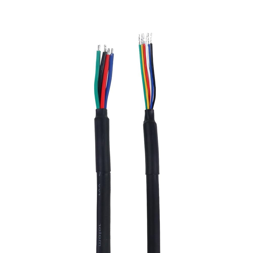
Figure 3: Motor and Encoder Cables. This image displays the two sets of cables provided with the kit, showing the individual colored wires for motor and encoder connections.
2.4.1 Motor and Encoder Connection Diagram
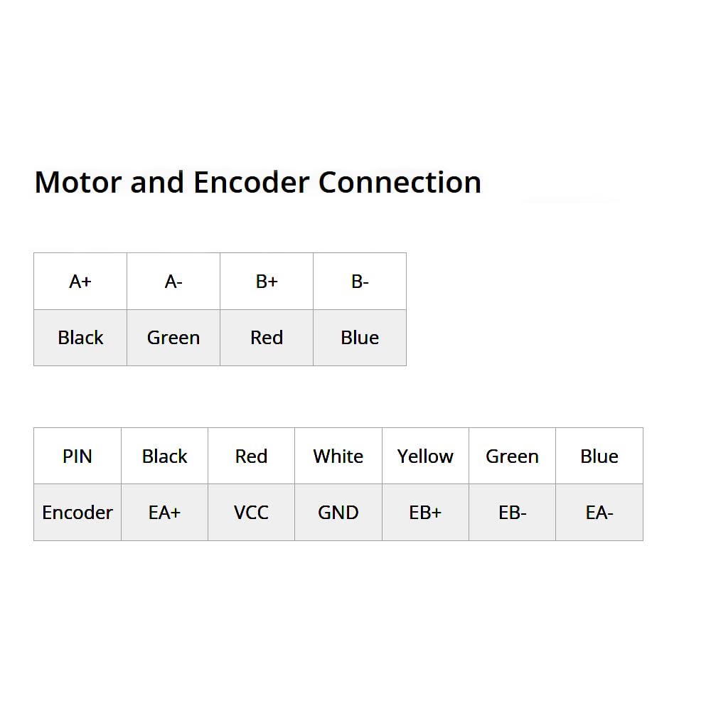
Figure 4: Motor and Encoder Connection Table. This diagram provides a clear mapping of wire colors to their respective motor and encoder terminals (A+, A-, B+, B- for motor; EA+, VCC, GND, EB+, EB-, EA- for encoder).
Refer to the table below and Figure 4 for correct wiring:
| Terminal | Wire Color |
|---|---|
| A+ | Black |
| A- | Green |
| B+ | Red |
| B- | Blue |
| PIN | Wire Color |
|---|---|
| EA+ | Black |
| VCC | Red |
| GND | White |
| EB+ | Yellow |
| EB- | Green |
| EA- | Blue |
2.4.2 Power Supply Connection
- Connect the power supply to the AC/DC terminals on the CL86Y driver.
- Input Voltage: 20-80VAC or 30-110VDC. A typical operating voltage is 48VDC or 60VDC.
- Ensure the power supply is capable of providing the required current for the motor (up to 8.5A peak output from the driver).
2.4.3 Control Signal Connection
- Connect your controller's pulse (PU+ / PU-), direction (DR+ / DR-), and enable (MF+ / MF-) signals to the corresponding terminals on the CL86Y driver.
- The logic signal current is typically 10mA (range 7-16mA).
2.5 Driver Configuration (DIP Switches)
The CL86Y driver uses DIP switches (SW1-SW6) to configure microstep resolution and pulse/direction mode.
2.5.1 Pulse/Revolution Table (Microstep Settings)
Use SW2, SW3, SW4, SW5, and SW6 to set the desired microstep resolution. The table below shows common settings:
| Pulse/rev | SW2 | SW3 | SW4 | SW5 | SW6 |
|---|---|---|---|---|---|
| 800 | ON | ON | ON | ON | ON |
| 1600 | ON | ON | ON | ON | OFF |
| 3200 | OFF | ON | ON | ON | ON |
| 6400 | ON | OFF | ON | ON | ON |
| 12800 | OFF | OFF | OFF | ON | ON |
| 25600 | ON | OFF | OFF | ON | ON |
| 51200 | OFF | OFF | ON | ON | ON |
| 1000 | ON | ON | OFF | OFF | OFF |
| 2000 | OFF | ON | OFF | OFF | OFF |
| 4000 | ON | OFF | OFF | OFF | OFF |
| 5000 | OFF | OFF | OFF | OFF | OFF |
| 8000 | ON | ON | ON | OFF | OFF |
| 10000 | OFF | ON | ON | OFF | OFF |
| 20000 | ON | OFF | ON | OFF | OFF |
| 40000 | OFF | OFF | OFF | OFF | OFF |
Note: The maximum step count is 40,000 steps, allowing for extremely accurate operation with encoder feedback.
2.5.2 Pulse/Direction Mode (SW1)
- SW1: OFF = PU+DR- (Pulse/Direction mode where Pulse is positive and Direction is negative)
- SW1: ON = CW/CCW (Clockwise/Counter-Clockwise mode)
3. Operating Instructions
3.1 Power On Sequence
- Ensure all wiring connections are correct and secure.
- Apply power to the CL86Y driver. The ALARM/PWR indicator should light up, indicating power is supplied.
- The motor will briefly engage and then settle, ready to receive commands.
3.2 Sending Control Signals
- The driver accepts pulse signals from your motion controller. The pulse input frequency can be up to 200kHz.
- The pulse width should be at least 2.5µS.
- The direction signal determines the rotation direction of the motor.
- The enable signal (MF) can be used to activate or deactivate the motor. When disabled, the motor will be free-spinning.
3.3 Closed Loop Operation
The integrated encoder provides real-time position feedback to the CL86Y driver. This allows the driver to detect and correct any position errors, ensuring that the motor maintains its commanded position without losing steps, even under varying loads. This results in higher accuracy and reliability compared to open-loop stepper systems.
4. Maintenance
The STEPPERONLINE Closed Loop Stepper Motor Kit is designed for durability and requires minimal maintenance. Adhere to the following guidelines to ensure optimal performance and longevity:
- Keep Clean: Regularly clean the motor and driver to prevent dust and debris accumulation, which can affect cooling and component lifespan. Use a soft, dry cloth.
- Check Connections: Periodically inspect all wiring connections for tightness and signs of wear or corrosion. Loose connections can lead to intermittent operation or damage.
- Environmental Conditions: Ensure the operating environment is within the specified temperature and humidity ranges to prevent overheating or condensation.
- Ventilation: Ensure adequate airflow around the driver and motor, especially if they are enclosed, to dissipate heat effectively.
5. Troubleshooting
If you encounter issues with your STEPPERONLINE Closed Loop Stepper Motor Kit, refer to the following common problems and solutions:
- Motor Not Moving or Erratic Movement:
- Verify all motor and encoder wiring connections are correct and secure.
- Check the power supply voltage and current to ensure it meets the driver's requirements.
- Confirm that the control signals (Pulse, Direction, Enable) from your controller are correctly connected and functioning.
- Ensure the microstep settings on the CL86Y driver (DIP switches SW2-SW6) are configured as desired.
- Check the ALARM/PWR indicator on the driver. If it's indicating an alarm, consult the driver's specific alarm codes (if available in the full product documentation).
- Motor Overheating:
- Ensure adequate ventilation around the motor and driver.
- Verify that the motor's rated current is not being exceeded.
- Reduce the load on the motor if possible.
- Loss of Steps (despite closed-loop):
- While rare in closed-loop systems, extreme loads or very high speeds can still cause issues. Ensure the motor is not operating beyond its torque or speed limits.
- Check encoder cable integrity. Damage to the encoder cable can disrupt feedback.
If the problem persists after attempting these solutions, please contact STEPPERONLINE customer support for further assistance.
6. Specifications
6.1 Motor Specification (34HS59-6004D-E1K-1M5)
| Parameter | Value |
|---|---|
| Manufacturer Part Number | 34HS59-6004D-E1K-1M5 |
| Motor Type | Bipolar Stepper |
| Step Angle | 1.8 degrees |
| Holding Torque | 12.00Nm (1699.34oz.in) |
| Rated Current/phase | 6.0A |
| Phase Resistance | 0.59 ohms ± 10% |
| Inductance | 4.8mH ± 20% (1KHz) |
| Insulation Class | B 130°C [266°F] |
| Frame Size | 86 x 86mm |
| Body Length | 174mm |
| Shaft Diameter | Φ14mm |
| Shaft Length | 37mm |
| D-Cut Length | 25mm |
| Cable Length | 1500mm |
| Output Circuit Type | Differential type |
| Encoder Type | Optical Incremental |
| Encoder Resolution | 1000PPR (4000CPR) |
| Encoder Supply Voltage Min | 4V |
| Encoder Supply Voltage Max | 5V |
| Encoder Output Current | 100mA |
| Encoder Output High Voltage | 5V |
| Encoder Output Low Voltage | 4.5V |
| Encoder Output Frequency Max | 60kHZ |
6.2 Driver Specification (CL86Y)
| Parameter | Value |
|---|---|
| Output Peak Current | 0~8.5A (0~6 RMS) |
| Input Voltage | 20~80VAC / 30~110VDC (Typical 48/60VDC) |
| Logic Signal Current | 7~16mA (Typical 10mA) |
| Pulse Input Frequency | 0~200kHz |
| Pulse Width | 2.5µS |
| Isolation Resistance | 500MΩ |
| Microstep Resolutions | 800 - 40000 (16 subdivisions) |
7. Warranty and Support
7.1 Warranty Information
For detailed warranty information regarding your STEPPERONLINE Closed Loop Stepper Motor Kit, please refer to the product's purchase documentation or contact STEPPERONLINE customer service directly. Warranty terms typically cover manufacturing defects for a specified period from the date of purchase.
7.2 Customer Support
If you require technical assistance, have questions about installation, operation, or troubleshooting that are not covered in this manual, please contact STEPPERONLINE customer support. You can often find support contact information on the official STEPPERONLINE website or through the retailer where the product was purchased.
Visit the official STEPPERONLINE store for more products and support resources: STEPPERONLINE Amazon Store


