
1. Introduction
This manual provides essential information for the safe installation, operation, and maintenance of your PowMr Hybrid Solar Inverter 12000W. Please read this manual thoroughly before installation and operation to ensure optimal performance and safety. Keep this manual for future reference.
2. Safety Information
WARNING: This inverter generates high voltage. Installation and maintenance must be performed by qualified personnel only. Failure to follow these instructions may result in serious injury or death.
- Do not attempt to disassemble or repair the inverter yourself. Contact qualified service personnel.
- Ensure all wiring is correctly sized and installed according to local and national electrical codes.
- Disconnect all power sources (PV, battery, AC input) before performing any maintenance or wiring.
- Install the inverter in a well-ventilated, dry, and cool environment, away from flammable materials.
- Ensure proper grounding of the inverter.
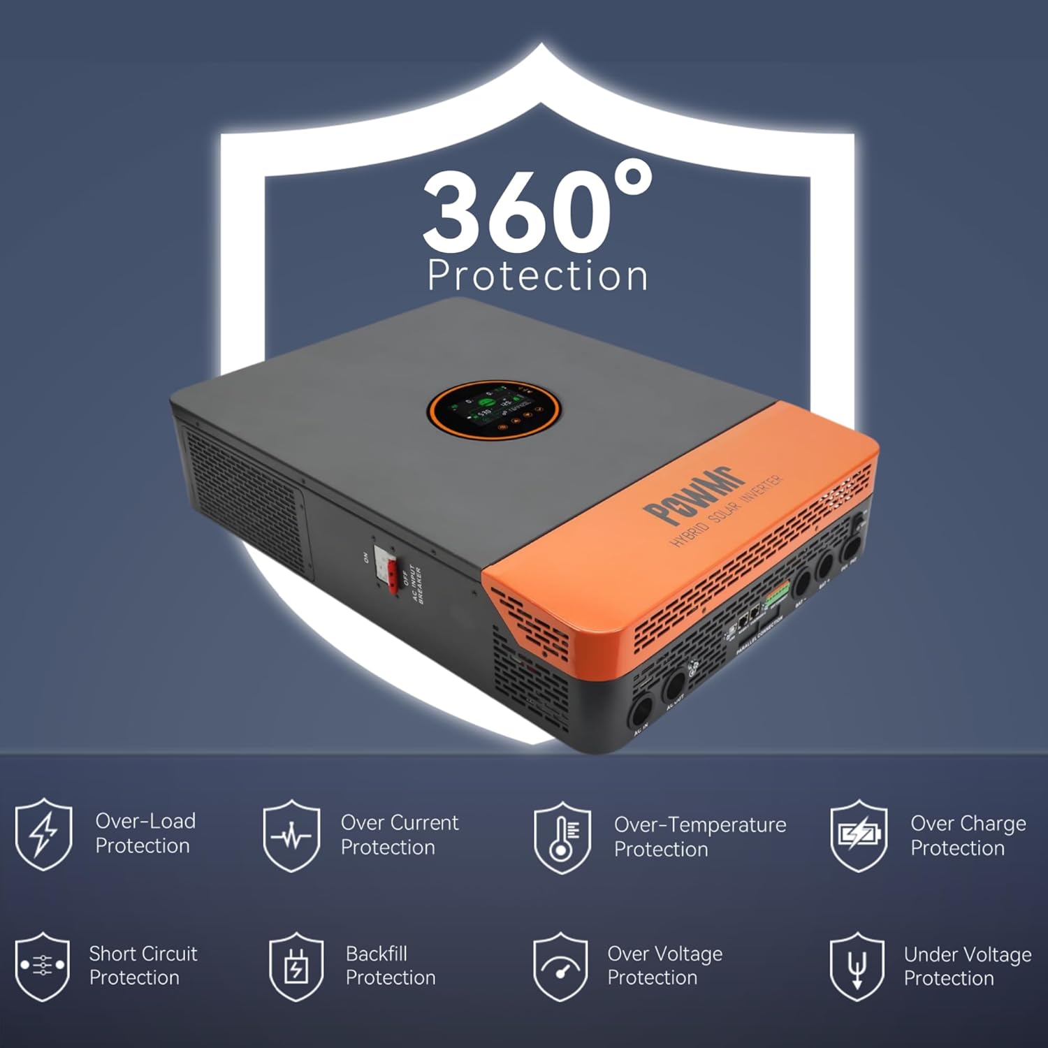
Figure 2.1: The inverter features comprehensive protection against over/under voltage, overload, short circuit, over-temperature, and anti-backfeed.
3. Product Overview
3.1 Key Features
- Output: 12000W continuous (24000W peak), 120/240Vac split-phase output.
- PV Input: Maximum 6600W PV input power, 500V DC maximum, 22A. PV starting voltage: ≥150V.
- MPPT Charger: Dual 100A MPPT chargers, max 200A charge current.
- Battery Compatibility: Supports 48V Li-ion, Lead-Acid, and user-defined battery types.
- Battery-Less Mode: Capable of powering loads directly from PV/AC without a battery connected.
- Parallel Operation: Supports up to 6 units in parallel for increased power output.
- Monitoring: Large LCD display, dynamic flow diagrams, and optional WiFi for remote monitoring via mobile app.
- Communication Ports: RS485, CAN, USB interfaces for integration with battery BMS, generator ATS, and smart home systems.

Figure 3.1: Overview of the 12KW Split-Phase Hybrid Solar Inverter's main features and capabilities.
3.2 Product Appearance and Components
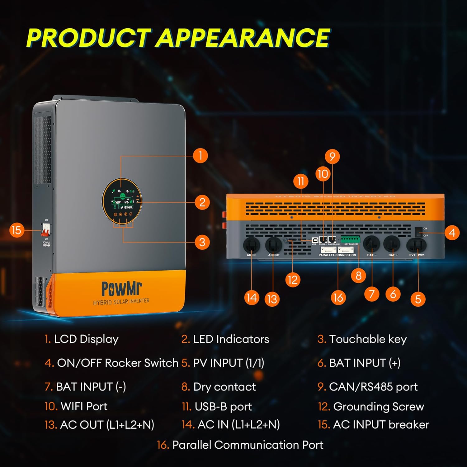
Figure 3.2: Front and side view of the inverter with labeled components.
- LCD Display
- LED Indicators
- Touchable Key
- ON/OFF Rocker Switch
- PV INPUT (1/1)
- BAT INPUT (+)
- BAT INPUT (-)
- Dry Contact
- CAN/RS485 Port
- WIFI Port
- USB-B Port
- Grounding Screw
- AC OUT (L1+L2+N)
- AC IN (L1+L2+N)
- AC INPUT Breaker
- Parallel Communication Port
4. Setup and Installation
4.1 Unpacking and Inspection
Upon receiving the inverter, carefully unpack it and inspect for any shipping damage. Ensure all components listed in the package contents are present:
- Solar inverter unit
- Parallel communication cable
- 2 × battery terminal lugs
- 2 × M5 screws
- User manual
Note: WiFi module, batteries, adapters, solar/battery wires/cables are excluded and require additional purchase if needed.
4.2 Mounting the Inverter
The inverter is designed for indoor (IP20) installation. Choose a mounting location that is:
- Vertical, on a solid surface capable of supporting the inverter's weight (approximately 27kg / 59.5lbs).
- Well-ventilated to allow for heat dissipation.
- Protected from direct sunlight, moisture, and dust.
- Accessible for wiring and maintenance.
4.3 Wiring Connections
All wiring must comply with local electrical codes. Use appropriate wire gauges for all connections.
- Grounding: Connect the grounding screw (12) to a reliable earth ground.
- Battery Connection: Connect the 48V battery bank to the BAT INPUT (+) (6) and BAT INPUT (-) (7) terminals. Ensure correct polarity.
- PV Input: Connect the solar panel array to the PV INPUT (1/1) (5) terminals. Observe correct polarity and ensure PV voltage is within specified limits (Max 500V DC, starting voltage ≥150V). Use 10AWG PV wire.
- AC Input: Connect the utility grid or generator AC input to the AC IN (L1+L2+N) (14) terminals.
- AC Output: Connect your loads to the AC OUT (L1+L2+N) (13) terminals. The inverter provides 120/240Vac split-phase output.
- Parallel Communication (Optional): If installing multiple inverters in parallel, connect the Parallel Communication Port (16) between units using the provided cable.
- Other Connections: Utilize RS485, CAN, USB, and dry contact ports (8, 9, 10, 11) for external communication and control as needed.

Figure 4.1: Example of multiple inverters connected in parallel. Professional guidance is required for actual connections.
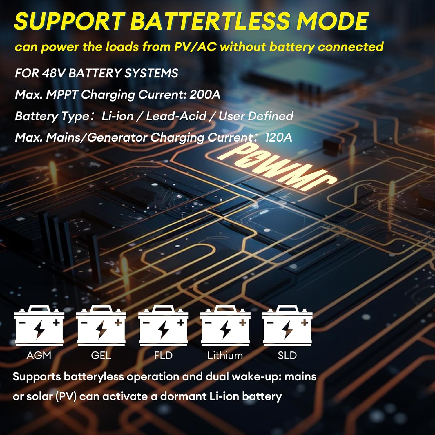
Figure 4.2: The inverter supports various 48V battery systems, including battery-less operation.
5. Operating Instructions
5.1 Powering On/Off
- Ensure all wiring connections are secure and correct.
- Switch on the battery breaker, then the PV breaker.
- Flip the ON/OFF Rocker Switch (4) to the 'ON' position.
- Switch on the AC INPUT Breaker (15).
- To power off, reverse the sequence: AC INPUT Breaker off, ON/OFF Rocker Switch off, PV breaker off, battery breaker off.
5.2 LCD Display and Settings
The large LCD display (1) provides real-time energy visualization and system status. Use the touchable keys (3) to navigate menus and adjust settings. Refer to the detailed settings section in the full user manual for specific parameter configurations, including:
- Battery charging parameters (voltage, current)
- Output voltage and frequency
- Operating modes (e.g., Solar First, Utility First, Battery First)
- Time-of-Use (TOU) control for smart charging/discharging
5.3 Battery-Less Mode
The inverter supports battery-less operation, allowing it to power loads directly from solar PV and/or AC input without a connected battery. This mode is useful for specific applications or during battery maintenance. Ensure proper configuration through the LCD settings.
6. Maintenance
Regular maintenance ensures the longevity and optimal performance of your inverter.
- Cleaning: Periodically clean the inverter's exterior and ventilation openings to prevent dust buildup, which can impede cooling. Use a dry, soft cloth.
- Connections: Annually inspect all electrical connections for tightness and signs of corrosion. Re-tighten if necessary.
- Environment: Ensure the installation environment remains within specified temperature and humidity ranges.
- Firmware: Check the manufacturer's website for any available firmware updates. Firmware updates can improve performance and address known issues.
WARNING: Always disconnect all power sources before performing any cleaning or inspection.
7. Troubleshooting
This section provides solutions to common issues. For problems not listed here, contact customer support.
| Problem | Possible Cause | Solution |
|---|---|---|
| Inverter does not power on | No battery connection or low battery voltage; DC breaker off; ON/OFF switch off. | Check battery connections and voltage; ensure DC breaker is on; turn ON/OFF switch to 'ON'. |
| No AC output | Overload; short circuit; AC output breaker tripped; inverter fault. | Reduce load; check for short circuits; reset AC output breaker; check LCD for error codes. |
| PV input not charging batteries | PV voltage too low or too high; PV polarity reversed; PV breaker off; MPPT fault. | Check PV voltage and polarity; ensure PV breaker is on; check LCD for PV error codes. |
| Unstable output in parallel mode | Incorrect parallel communication wiring; mismatched firmware versions; incompatible settings. | Ensure only one parallel communication cable is used between units. Verify all inverters have the same, latest firmware version. Check parallel settings on each inverter. Contact support if issues persist. |
| Inverter displays error code | Internal fault; external condition (e.g., over-temperature, over-voltage). | Refer to the full manual's error code section for specific meanings and solutions. Address environmental conditions if applicable. |
8. Specifications
| Parameter | Value |
|---|---|
| Model Name | BI-POW-SunSmart 12KP |
| Rated Output Power | 12000W (12KW) |
| Peak Power | 24000W |
| Rated Output Voltage | 120/240Vac (Split-Phase/Single-Phase) |
| Battery Voltage | 48V |
| Maximum PV Input Power | 6600W |
| Maximum PV Input Voltage | 500V DC |
| Maximum PV Input Current | 22A |
| PV Starting Voltage | ≥150V |
| MPPT Charge Current | Dual 100A (Max 200A total) |
| Max. Mains/Generator Charging Current | 120A |
| Communication Ports | RS485, CAN, USB |
| Dimensions (L×W×H) | 24.41 × 17.52 × 5.12 inches (62 × 44.5 × 13 cm) |
| Weight | 59.5 lbs (27 kg) |
| Protection Rating | IP20 (Indoor use) |
9. Warranty and Support
For warranty information, please refer to the documentation provided with your purchase or contact PowMr customer service. For technical support, troubleshooting assistance, or inquiries regarding parts and service, please visit the official PowMr website or contact their customer support channels.
Online Resources:
- PowMr Store on Amazon: Visit PowMr Store