1. Product Overview
The WALFRONT 36CH RGBW DMX512 Decoder is designed to convert DMX512 digital signals into analog signals for controlling RGBW LED lighting. This device supports up to 36 output channels, offering precise dimming control and versatile compatibility for various LED strip applications in DJ and stage lighting setups.
Key Features
- Multiple Output Channels: Supports up to 36 output channels for versatile compatibility with single and RGBW LED strips.
- Precision Dimming Control: Features a dimming range of 0 to 100% with 256 grayscale levels for optimal lighting effects.
- Convenient Digital Display: Easy address code identification via a clear digital display for simplified setup.
- Robust Power Support: Handles a maximum power load of 864W at 12V and 1728W at 24V for extensive applications.
- Built-in Test Modes: Includes 14 test modes with 10 change rate levels for creative lighting experimentation.
Package Contents
- 1 x Digital Multiple X Decoder
- 1 x Power Plug
- 1 x Terminal Block Set
2. Setup Instructions
2.1 Component Identification
Familiarize yourself with the various components and connection points of the DMX512 Decoder.

Figure 2.1: Top view of the DMX512 Decoder. Observe the input terminals on the right, output terminals on the left, DMX IN/OUT ports, digital display, and control buttons (M, +, -) in the center.

Figure 2.2: Angled view of the DMX512 Decoder. This perspective shows the DMX IN and DMX OUT ports, along with the DC power input terminals.
2.2 Power Connection
Connect a DC 9V to 24V power supply to the 'INPUT' terminals on the right side of the decoder. Ensure correct polarity (+ to + and - to -) to prevent damage to the device.
2.3 DMX Signal Connection
Connect your DMX512 controller to the 'DMX IN' port using a standard DMX cable. If daisy-chaining multiple decoders, connect the 'DMX OUT' of this decoder to the 'DMX IN' of the next device.

Figure 2.3: DMX IN and DMX OUT connectors. These are used to establish the DMX signal chain.
2.4 LED Strip Connection
Connect your RGBW LED strips to the 'OUTPUT' terminals. The decoder provides 36 channels, typically grouped into 9 sets of RGBW outputs (V+, R, G, B, W). Ensure that the common anode (V+) of the LED strip is connected to the V+ terminal and the respective color channels (R, G, B, W) are connected to their corresponding terminals.
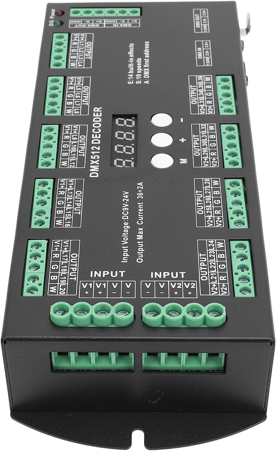
Figure 2.4: Front view of the decoder, illustrating the arrangement of the 36 output channels for connecting RGBW LED strips.
3. Operating Instructions
3.1 Digital Display and Control Buttons
The decoder features a digital display and three control buttons: 'M' (Mode), '+' (Increase), and '-' (Decrease).
- 'M' Button: Press to switch between DMX address setting mode and built-in test mode selection.
- '+' Button: Increases the DMX address value or cycles through test modes/speeds.
- '-' Button: Decreases the DMX address value or cycles through test modes/speeds.
3.2 Setting DMX Address
- Ensure the decoder is powered on. The digital display will show the current DMX address.
- If the display shows 'E' followed by a number (test mode), press the 'M' button until a three-digit number (DMX address) is displayed.
- Use the '+' and '-' buttons to adjust the DMX starting address to your desired value (1-512).
- The setting will automatically save after a few seconds of inactivity.
3.3 Using Built-in Test Modes
- Press the 'M' button until the display shows 'E' followed by a number (e.g., 'E01'). This indicates the test mode selection.
- Use the '+' and '-' buttons to cycle through the 14 available built-in test modes (E01 to E14).
- Some test modes allow for speed adjustment. After selecting a test mode, press 'M' again to enter speed adjustment mode (display may show 'S' followed by a number). Use '+' and '-' to select from 10 change rate levels.
- The setting will automatically save after a few seconds of inactivity.
4. Maintenance
To ensure the longevity and optimal performance of your WALFRONT DMX512 Decoder, follow these maintenance guidelines:
- Cleaning: Regularly wipe the exterior of the device with a soft, dry cloth. Avoid using harsh chemicals, solvents, or abrasive cleaners.
- Environment: Operate and store the decoder in a dry, well-ventilated area, away from direct sunlight, extreme temperatures, and high humidity.
- Connections: Periodically check all power and signal connections to ensure they are secure and free from corrosion.
- Ventilation: Ensure that the ventilation openings (if any) are not obstructed to prevent overheating.
- Power Off: Always disconnect power before performing any cleaning or maintenance.
5. Troubleshooting
If you encounter issues with your DMX512 Decoder, refer to the following common problems and solutions:
- No Power:
- Check if the power supply is correctly connected and providing the specified DC 9V-24V.
- Verify that the power outlet is functional.
- Ensure power cable is not damaged.
- No DMX Signal/LEDs Not Responding:
- Confirm that the DMX cable is securely connected to 'DMX IN' and to your DMX controller.
- Check the DMX address setting on the decoder matches the address set on your DMX controller.
- Ensure the DMX controller is transmitting a signal.
- Verify DMX cable integrity.
- Incorrect LED Output/Flickering:
- Check the wiring of the LED strips to the output terminals for correct polarity and channel assignment (V+, R, G, B, W).
- Ensure the power supply is sufficient for the connected LED load.
- If using built-in test modes, ensure the correct mode and speed are selected.
- Digital Display Not Working:
- Ensure the device is receiving power.
- If the issue persists, contact customer support.
6. Technical Specifications
| Feature | Specification |
|---|---|
| Item Type | Digital Multiple X Decoder |
| Material | Plastic |
| Input Voltage | DC 9V to DC 24V |
| Output Channels | 36 Channels (RGBW) |
| Output Max Current | 36 * 2A |
| Maximum Power (12V) | 864W |
| Maximum Power (24V) | 1728W |
| Dimming Range | 0-100% (256 grayscale levels) |
| Built-in Test Modes | 14 modes with 10 change rate levels |
| Product Size | Approx. 88x38x219mm / 3.46x1.50x8.62in |
| Item Weight | Approx. 722g / 25.5oz (1.59 pounds) |
| Model Number | WALFRONTkno890xgsg |
7. Warranty and Support
For warranty information or technical support, please refer to the retailer's return policy or contact Walfront customer service directly. Keep your purchase receipt for warranty claims.
For further assistance, please visit the Walfront Store on Amazon.
