
1. Introduction
Thank you for choosing the Blütezeit MJ-300 Sliding Gate Opener. This system is designed to provide reliable and convenient automation for residential sliding gates weighing up to 900 lbs. Featuring a quiet rack-driven mechanism, durable nylon gear racks, and secure rolling-code remote controls, the MJ-300 offers enhanced security and ease of use for your property. Please read this manual thoroughly before installation and operation to ensure proper function and safety.
2. Safety Information
Improper installation or use can cause serious injury or property damage. Always follow these safety guidelines:
- Read all instructions: Familiarize yourself with the entire manual before beginning installation or operation.
- Qualified personnel: Installation and wiring should be performed by qualified personnel.
- Power supply: Disconnect power to the gate opener before performing any maintenance or repairs.
- Moving gate: Keep hands, feet, and clothing clear of the gate and gate opener at all times.
- Children and pets: Do not allow children or pets to play near the gate or gate opener.
- Obstacle detection: Ensure the obstacle-reverse protection system is functioning correctly.
- Emergency release: Know how to manually operate the gate in case of power failure or malfunction.
- Gate condition: Ensure the gate is in good working order, moves freely, and is properly balanced before installing the opener.
3. Package Contents
Verify that all components are present and undamaged:
- Blütezeit MJ-300 Sliding Gate Opener Unit (1)
- Reinforced Nylon Gear Racks (4 pieces, 3.28 ft each, total 13.12 ft)
- Rolling-Code Remote Controls (4)
- Mounting Hardware (screws, brackets, etc.)
- Red Magnet Switch (1)
- Blue Magnet Switch (1)
- User Manual (this document)
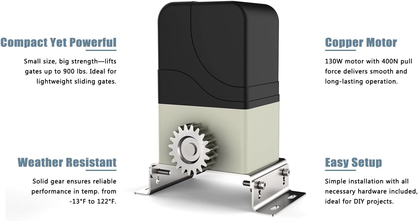
Figure 3.1: Blütezeit MJ-300 Gate Opener Unit. This image displays the compact gate opener motor with its gear, highlighting its weather-resistant design and copper motor.

Figure 3.2: Remote Controls and Magnet Switches. This image shows one of the secure rolling-code remote controls, along with the red and blue magnet switches used for precise gate open and close positioning.

Figure 3.3: Four Nylon Gear Racks. This image illustrates the four pieces of reinforced nylon gear racks included with the system, each measuring 3.28 ft.
4. Specifications
| Feature | Specification |
|---|---|
| Model | MJ-300 |
| Max. Gate Weight | 900 lbs (408 kg) |
| Motor Power | 130W AC110V Pure Copper Motor |
| Gear Rack Length | 13.12 ft (4 x 3.28 ft sections) |
| Gear Rack Material | Reinforced Nylon with Metal Core |
| Remote Control Frequency | 433.92 MHz (Rolling Code) |
| Max. Remote Controls Supported | 100 |
| Operating Temperature | -13°F to 122°F (-25°C to 50°C) |
| Auto-Close Timer | Programmable (0-60 seconds) |
| Special Features | Pedestrian Mode, Obstacle-Reverse Protection |
5. Setup & Installation
Before starting, ensure your gate is properly installed, moves freely, and is level. The installation process involves mounting the gate opener, installing the gear racks, and connecting the magnet switches.
5.1. Mounting the Gate Opener Unit
- Choose a stable, level mounting surface near the gate, ensuring the opener's gear aligns with the gate's future rack position.
- Securely fasten the gate opener unit to the mounting surface using appropriate hardware. Ensure it is firmly anchored to prevent movement during operation.
5.2. Installing the Gear Racks
The nylon gear racks attach to the gate and engage with the opener's gear to move the gate.
- Assemble the gear rack sections by sliding them together. The reinforced nylon design ensures durability and quiet operation.
- Position the assembled rack along the bottom edge of the gate, ensuring it is level and parallel to the ground. The rack should be at a height that allows the opener's gear to engage properly, with a small clearance (approx. 1-2mm) between the gear and the rack teeth.
- Mark the drilling points for the mounting screws on the gate.
- Drill pilot holes and securely attach the gear racks to the gate using the provided screw mounting hardware. Ensure all sections are firmly attached and aligned.

Figure 5.1: Gear Rack Connection Detail. This image shows how individual nylon gear rack sections connect to form a continuous track.

Figure 5.2: Gear Rack Dimensions. This image provides a visual representation of the gear rack dimensions, including its length (40 inches or 3.28 ft), width (3/4 inch), and height (1 inch).

Figure 5.3: Gear Rack Screw Mounting. This image demonstrates the screw mounting method for attaching the gear racks to the gate, showing the screws and washers used.
5.3. Installing Magnet Switches
The red and blue magnet switches define the gate's open and close limits.
- Attach the red magnet switch to the gate at the desired fully closed position. This magnet signals the opener to stop when the gate is closed.
- Attach the blue magnet switch to the gate at the desired fully open position. This magnet signals the opener to stop when the gate is open.
- Ensure the magnets are positioned correctly to activate the internal sensors of the gate opener at the precise open and close points.
5.4. Electrical Wiring
Connect the gate opener to a dedicated AC110V power supply. Refer to the wiring diagram provided in the separate installation guide for detailed instructions. Ensure all connections are secure and comply with local electrical codes. It is recommended that a qualified electrician perform this step.
5.5. Remote Control Programming
The MJ-300 comes with four pre-programmed rolling-code remote controls. If additional remotes are needed or if existing remotes need reprogramming, follow the instructions in the separate remote programming guide. The system supports up to 100 remote controls.
6. Operating Instructions
Once installed and powered, the gate opener is ready for operation.
6.1. Basic Gate Operation
- Press the designated button on your remote control to open or close the gate. The gate will move until it reaches the limit set by the magnet switches.
- Pressing the button again during operation will stop the gate. A subsequent press will reverse its direction.
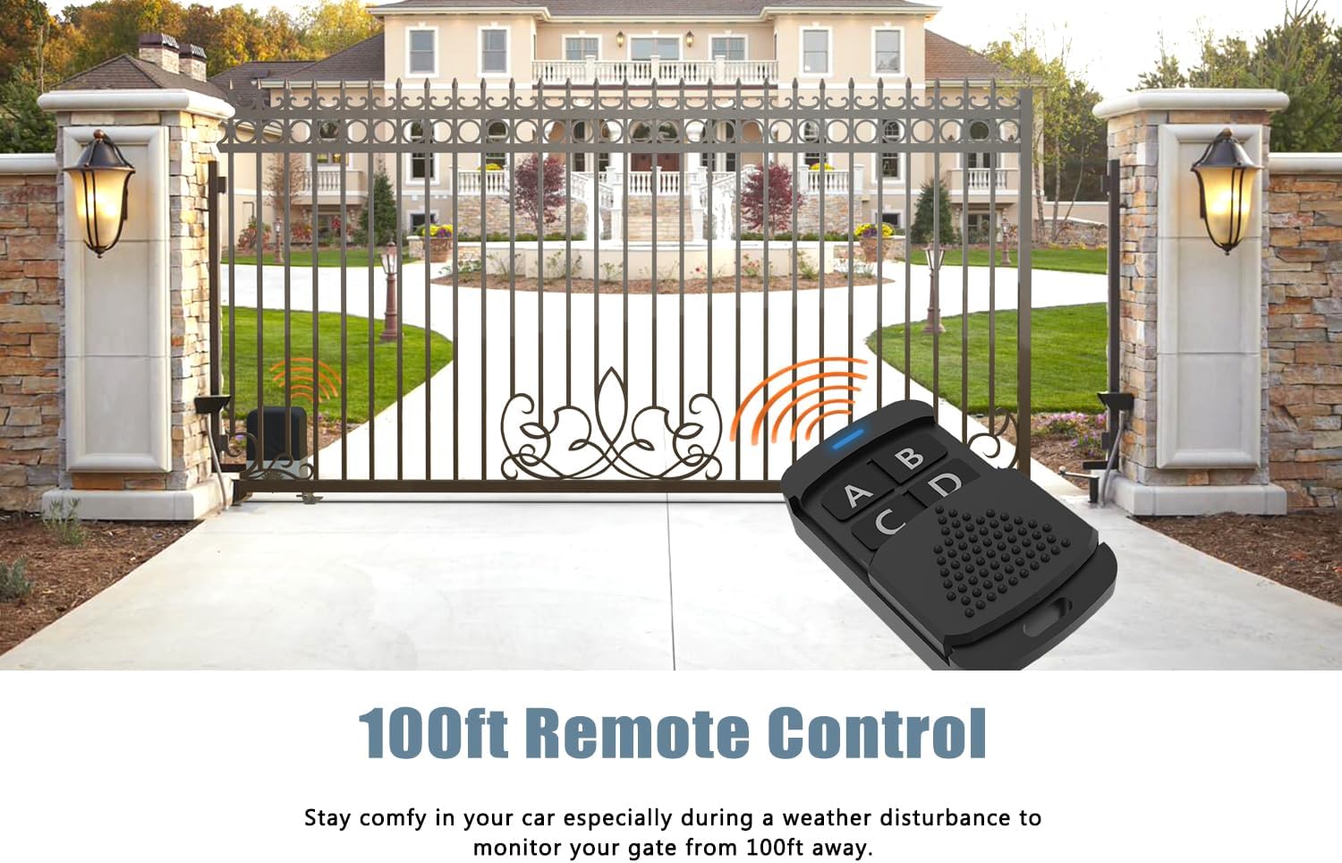
Figure 6.1: Remote Control in use with Gate. This image depicts a remote control being used to operate a sliding gate, illustrating the convenience of remote access from a distance of up to 100 feet.
6.2. Auto-Close Function
The auto-close function automatically closes the gate after a set period. This feature can be programmed for a delay of 0 to 60 seconds. Refer to the control board manual for specific programming steps.
6.3. Pedestrian Mode
Pedestrian mode allows the gate to open partially, providing access for foot traffic without fully opening the gate. This feature can be activated via a specific remote button or an optional wired input. Consult the control board manual for configuration.
6.4. Obstacle-Reverse Protection
The MJ-300 is equipped with an obstacle-reverse protection system. If the gate encounters an obstruction during closing, it will automatically reverse direction to prevent damage or injury. During opening, it will stop. Regularly test this safety feature to ensure it is functioning correctly.
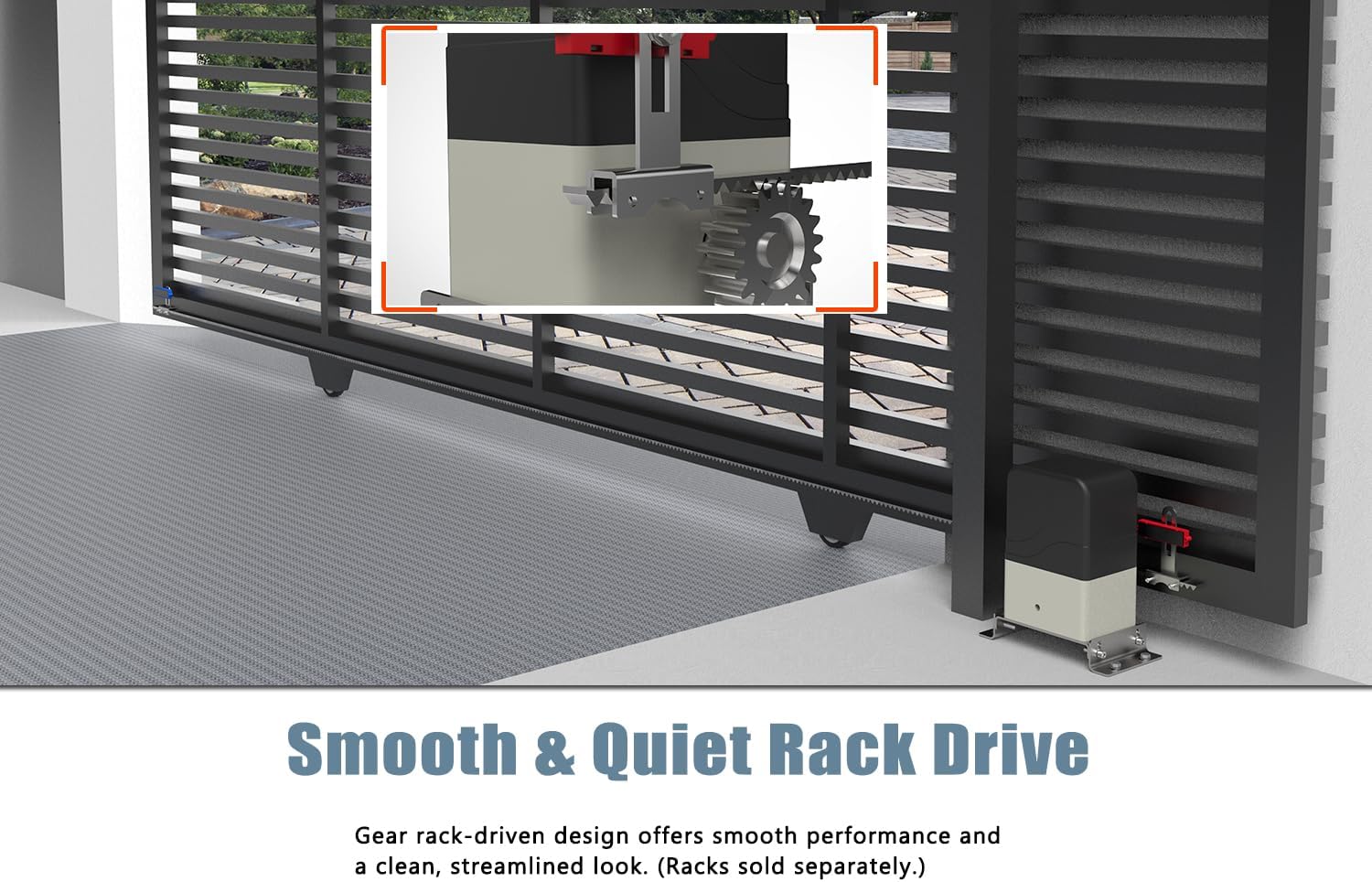
Figure 6.2: Smooth and Quiet Rack Drive in operation. This image shows the gate opener installed and operating a sliding gate, emphasizing the smooth and quiet movement provided by the rack-driven system.
7. Maintenance
Regular maintenance ensures the longevity and safe operation of your gate opener.
- Monthly:
- Inspect the gate for proper balance and free movement. Lubricate hinges and rollers if necessary.
- Check the gear racks for any damage or loose mounting screws.
- Test the obstacle-reverse protection system.
- Quarterly:
- Clean the gate opener unit exterior and ensure ventilation openings are clear.
- Inspect all electrical connections for corrosion or looseness (ensure power is disconnected first).
- Verify the magnet switches are securely in place and functioning correctly.
- Annually:
- Have a qualified technician inspect the entire system for wear and tear.
8. Troubleshooting
Refer to this section for common issues and their solutions. If the problem persists, contact customer support.
| Problem | Possible Cause | Solution |
|---|---|---|
| Gate does not respond to remote. | No power to opener; remote battery dead; remote not programmed; signal interference. | Check power supply; replace remote battery; reprogram remote; clear obstructions. |
| Gate stops unexpectedly or reverses. | Obstruction detected; limit switches misaligned; motor overload. | Remove obstruction; adjust magnet switches; check gate for free movement. |
| Gate opens/closes partially. | Limit switches incorrectly set or moved. | Adjust the red and blue magnet switches to define full open/close positions. |
| Unusual noise during operation. | Gear rack misalignment; worn components; debris in gear. | Inspect and adjust gear rack; clean gear; check for worn parts. |
| Auto-close not working. | Auto-close function disabled or timer set to 0. | Refer to control board manual to enable and set auto-close timer. |
9. Warranty & Support
Blütezeit products are manufactured to high-quality standards. For warranty information, technical support, or to purchase replacement parts, please contact Blütezeit customer service. Keep your purchase receipt as proof of purchase.
Contact Information: Please refer to the Blütezeit official website or your purchase documentation for the most current contact details.