1. Introduction
Thank you for choosing the VEVOR DP30016B-VS 750W Benchtop Drill Press. This manual provides essential information for the safe operation, assembly, maintenance, and troubleshooting of your new tool. Please read this manual thoroughly before initial use to ensure proper function and to prevent injury or damage. Keep this manual in a safe place for future reference.
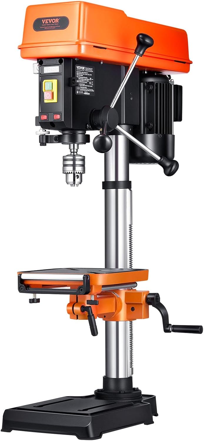
Figure 1.1: VEVOR DP30016B-VS 750W Benchtop Drill Press. This image shows the complete drill press unit from a front-right angle, highlighting its compact benchtop design.
2. General Safety Instructions
Always follow basic safety precautions to reduce the risk of fire, electric shock, and personal injury when operating power tools.
2.1 Work Area Safety
- Keep the work area clean and well-lit. Cluttered or dark areas invite accidents.
- Do not operate power tools in explosive atmospheres, such as in the presence of flammable liquids, gases, or dust. Power tools create sparks which may ignite the dust or fumes.
- Keep children and bystanders away while operating a power tool. Distractions can cause you to lose control.
2.2 Electrical Safety
- Power tool plugs must match the outlet. Never modify the plug in any way.
- Avoid body contact with earthed or grounded surfaces, such as pipes, radiators, ranges, and refrigerators. There is an increased risk of electric shock if your body is earthed or grounded.
- Do not expose power tools to rain or wet conditions. Water entering a power tool will increase the risk of electric shock.
2.3 Personal Safety
- Always wear eye protection. Use safety glasses, goggles, or a face shield.
- Dress properly. Do not wear loose clothing or jewelry. Keep your hair, clothing, and gloves away from moving parts.
- Stay alert, watch what you are doing, and use common sense when operating a power tool.
3. Components Included
The VEVOR DP30016B-VS Benchtop Drill Press package includes the following components:
- 1 x Base
- 1 x Table
- 1 x Drill Press (Main Unit)
- 4 x Feed Handles
- 1 x Lift Handle Assembly
- 1 x Column Assembly
- 1 x Wedge
- 2 x Table Lock Handle
- 3 x Hex Wrenches
- 4 x Hex Bolts
- 1 x Chuck with Key

Figure 3.1: Product Parameters and Components. This image illustrates the main components of the drill press and lists the included parts, providing a visual reference for assembly.
4. Setup and Assembly
Follow these steps to assemble your VEVOR Benchtop Drill Press:
- Unpack Components: Carefully remove all parts from the packaging. Verify that all components listed in Section 3 are present and undamaged.
- Attach Column to Base: Securely fasten the column assembly to the base using the provided hex bolts and wrenches. Ensure the column is firmly seated and stable.
- Install Table Assembly: Slide the table assembly onto the column. Position it at a suitable working height and secure it with the table lock handle.
- Mount Drill Press Head: Carefully place the drill press head (main unit) onto the top of the column. Ensure it is aligned correctly and secured according to the specific instructions in your packaging (refer to any included diagrams for precise alignment).
- Attach Feed Handles: Screw the feed handles into the drill press head. These handles control the vertical movement of the drill chuck.
- Install Chuck: Insert the chuck into the spindle. Use the chuck key to tighten the chuck securely.
- Secure to Workbench: For optimal stability and safety, it is highly recommended to bolt the drill press base to a sturdy workbench.
5. Operating Instructions
This section details the proper operation of your drill press for various tasks.
5.1 Power and Motor
The drill press is equipped with a 750W all-copper induction motor, designed for consistent performance and durability.

Figure 5.1: Motor Performance. This image highlights the 750W all-copper induction motor, emphasizing its high efficiency, low noise, and long lifespan for effortless drilling.
5.2 Variable Speed Adjustment
The drill press features a continuously variable speed control from 340 to 2200 RPM, displayed on a digital screen. Adjust the speed using the speed control lever located on the side of the drill head.
- Lower Speeds (340-800 RPM): Ideal for drilling large holes or hard materials like metal.
- Medium Speeds (800-1500 RPM): Suitable for general drilling and machining.
- Higher Speeds (1500-2200 RPM): Best for small diameter holes, softer materials, or thin materials.

Figure 5.2: Speed Adjustment Mechanism. This image shows the speed control lever and digital RPM display, illustrating how to adjust the continuous variable speed for different drilling applications.
5.3 X-Ray Positioning and LED Light
The integrated X-ray positioning system helps to accurately locate the drilling point, while the high-brightness LED light illuminates the entire work area for improved visibility, especially in low-light conditions.

Figure 5.3: Precision Positioning Features. This image demonstrates the X-ray positioning system, which projects crosshairs onto the workpiece, and the LED light for enhanced visibility during drilling.
5.4 Chuck and Drilling Capacity
The drill press features a chuck with a maximum drilling diameter of 16 mm. Ensure the drill bit is securely clamped in the chuck to minimize runout and slippage during operation.

Figure 5.4: Chuck and Drilling Capacity. This image illustrates the chuck's secure clamping mechanism and indicates the maximum drilling diameter of 16mm, ensuring minimal slippage.
5.5 Adjustable Work Table and Depth Limiter
The thick metal work table can be adjusted in height and tilted up to 45 degrees. An adjustable depth limiter allows for precise control over drilling depth, with a spindle travel of 90 mm.

Figure 5.5: Work Table Adjustments. This image shows the adjustable work table, highlighting its ability to be moved up/down and tilted up to 45 degrees for versatile drilling operations.
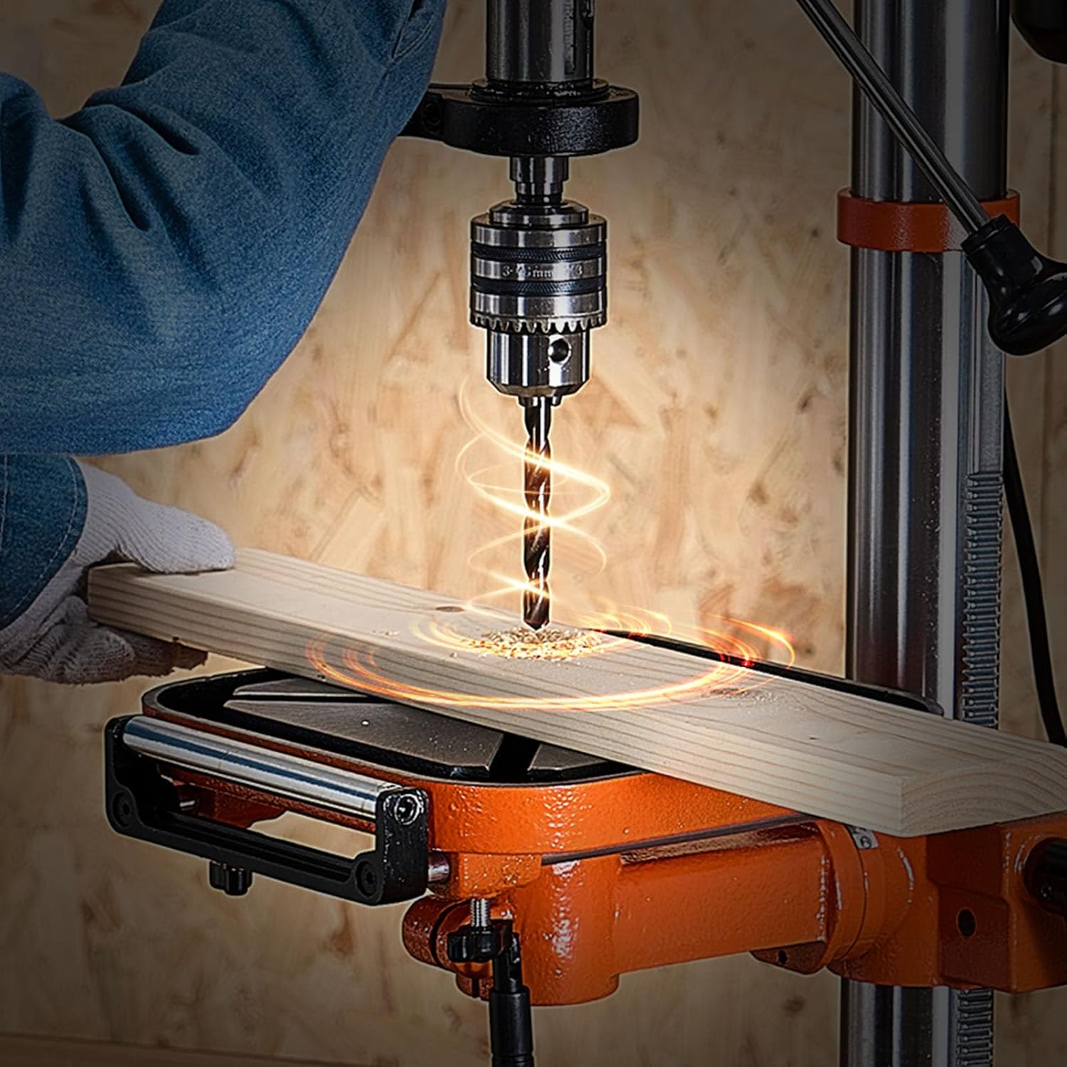
Figure 5.6: Drilling Operation. This image captures the drill press in action, demonstrating a drill bit penetrating a wooden workpiece, with emphasis on the precision and control offered by the machine.
6. Maintenance
Regular maintenance ensures the longevity and optimal performance of your drill press.
- Cleaning: After each use, disconnect the power and clean the machine thoroughly. Remove all dust, chips, and debris from the table, column, and head. Use a brush or compressed air.
- Lubrication: Periodically apply a light coat of machine oil to the column, spindle, and other moving parts to prevent rust and ensure smooth operation. Do not over-lubricate.
- Chuck Maintenance: Keep the chuck jaws clean and free of debris. If the chuck becomes stiff, clean it and apply a small amount of lubricant.
- Belt Tension: Check the drive belt tension periodically. Adjust if necessary according to the instructions in the motor housing.
- Inspection: Regularly inspect all bolts, nuts, and fasteners for tightness. Tighten any loose components. Check the power cord for any signs of damage.
7. Troubleshooting
This section addresses common issues you might encounter with your drill press.
| Problem | Possible Cause | Solution |
|---|---|---|
| Drill press does not start | No power supply Faulty switch | Check power connection and outlet Inspect power switch for damage |
| Excessive vibration during operation | Loose components Unbalanced drill bit Unsecured workpiece | Tighten all bolts and fasteners Replace or re-seat drill bit Secure workpiece firmly to table |
| Drill bit slips in chuck | Chuck not tightened sufficiently Dirty chuck jaws Damaged chuck jaws | Tighten chuck with key Clean chuck jaws Replace chuck if damaged |
| Inaccurate drilling | Loose column or table Worn drill bit Improper X-ray calibration | Ensure column and table are locked Use sharp, appropriate drill bits Verify X-ray alignment (refer to specific calibration instructions if available) |
8. Specifications
Key technical specifications for the VEVOR DP30016B-VS 750W Benchtop Drill Press:
| Feature | Specification |
|---|---|
| Model Number | DP30016B-VS |
| Maximum Power | 750 W |
| Spindle Speed | 340-2200 RPM (Continuously Variable) |
| Chuck Capacity | ≤ 16 mm |
| Spindle Travel | 90 mm |
| Swing | 12 in / 304.8 mm |
| Work Table Tilt | 0 to 45° |
| Voltage | 220 Volt |
| Power Source | Corded Electric |
| Product Dimensions (L x W x H) | 56.8 x 36.5 x 95 cm (22.4 x 14.37 x 37.4 in) |
| Net Weight | 39.5 kg (87.06 lbs) |
| Main Material | Q235, HT150 |
9. Warranty and Support
VEVOR products are designed and manufactured to high-quality standards. For warranty information, technical support, or service inquiries, please refer to the warranty card included with your product or visit the official VEVOR website. Please have your model number (DP30016B-VS) and purchase date available when contacting support.