1. Introduction
This manual provides detailed instructions for the installation, operation, and maintenance of your GLEDOPTO Elite 4-Channel ESP32 WLED LED Strip Light Controller. This advanced controller offers versatile control over addressable LED strips, featuring Ethernet and WiFi connectivity, sound reactivity, and energy-saving capabilities.
What's in the Box
- 1x GLEDOPTO Elite 4-Channel ESP32 WLED LED Strip Light Controller (Black Shell)
2. Setup
2.1 Wiring Connections
Ensure all power is disconnected before making any wiring connections. The controller supports DC 5-24V input. Connect your addressable LED strips to the four independent output terminals. Observe correct polarity (V+ and GND) and data lines (IO pins).
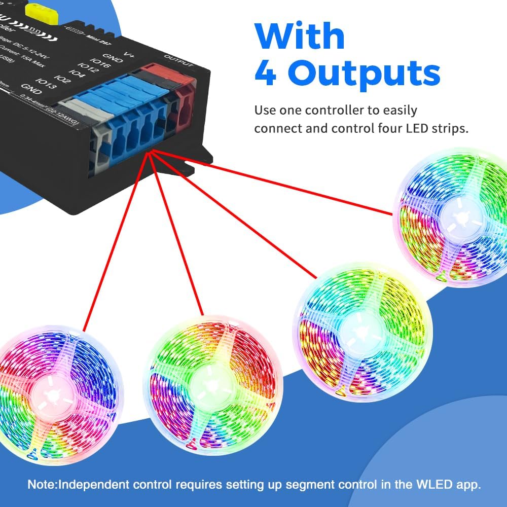
Image: The GLEDOPTO Elite 4-Channel Controller demonstrating connections to four separate LED strips. Each strip is independently controlled.
2.2 Quick Connect Port Design
The controller features quick-connect Wago terminals for easy and secure wiring. To connect a wire:
- Open the connector lever upwards.
- Insert the stripped wire into the terminal.
- Press the lever down to secure the wire.

Image: Visual guide for using the quick-connect Wago terminals on the controller.
2.3 Network Connectivity (Ethernet & WiFi)
The controller offers both wired Ethernet and wireless WiFi connectivity for flexible installation and control.
- Ethernet: For a stable wired connection, plug an Ethernet cable into the designated port. This allows for quick connection to the WLED app or web interface.
- WiFi: For wireless convenience, the controller can connect to your local WiFi network. Initial setup typically involves connecting to the controller's own WLED-AP hotspot, then configuring it to join your home network via the WLED app.

Image: The controller highlighting its dual network connectivity options: wired Ethernet and wireless WiFi.
3. Operating Instructions
3.1 WLED App / PC Web Control
The GLEDOPTO Elite controller is designed to work with the WLED software, accessible via a mobile app or a PC web interface. This allows for comprehensive control over your LED strips.

Image: The WLED app interface on a smartphone, demonstrating color and effect selection for LED strips.
3.2 Segmented Color Control
Utilize the WLED software to personalize every segment of your LED strips. This feature allows you to create different lighting scenes and effects on various sections of a single LED strip or across multiple strips connected to the four outputs.
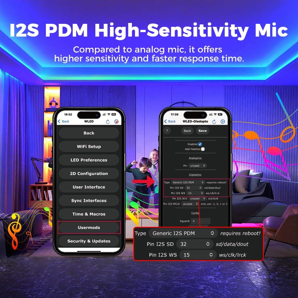
Image: The WLED app displaying options for segmented control, allowing users to define and manage different lighting zones.
3.3 Sound Reactive Lighting
The built-in I2S PDM high-sensitivity microphone enables your LED lights to dynamically sync with ambient sound or music, creating immersive audio-reactive effects. Configure microphone settings within the WLED app under "Usermods".

Image: The WLED app interface showing the microphone configuration settings for sound-reactive lighting.
Video: Demonstration of the GLEDOPTO Elite 4-Output ESP32 WLED LED Controller with Ethernet, showcasing various lighting effects and functionalities.
3.4 All-in-One Function Button
The controller features a multi-function button for quick actions:
- Short press: Power on/off.
- Long press for 1 second: Switch colors.
- Long press for 10 seconds: Reset the WLED controller and activate the WLED-AP hotspot for initial setup or re-configuration.

Image: Illustration detailing the functions of the single button on the GLEDOPTO controller.
4. Features Overview
4.1 Versatile Quad-Channel LED Control
This controller features 4 independent outputs for simultaneous control of multiple LED strips. It supports popular addressable LED types such as WS2811, WS2812, SK6812, and WS2815, allowing for a vast library of dynamic lighting effects through the WLED software.

Image: Examples of different addressable LED strip types compatible with the GLEDOPTO controller.
4.2 Energy-Saving Relay
The integrated energy-saving relay minimizes power consumption in standby mode. When the LED strips are turned off, the relay ensures no current passes through them, significantly reducing standby power usage compared to controllers without this feature.

Image: Visual comparison illustrating the power saving benefits of the integrated relay.
Video: A demonstration highlighting how a relay switch can cut standby power, leading to energy savings.
4.3 20A Pluggable Fuse
For enhanced reliability and safety, the controller includes a 20A pluggable fuse. This fuse provides overcurrent protection, safeguarding the device and connected LED strips from damage due to excessive current. If the fuse blows, it can be easily replaced.

Image: Detailed view of the controller's internal components, pointing out the 20A pluggable fuse for circuit protection.
4.4 UART Interface
The accessible UART interface allows for updating the WLED firmware, ensuring your controller always has the latest features and improvements. This is typically done via a Type-C USB connection to a PC.

Image: The controller connected to a laptop via its Type-C port, illustrating the UART interface for firmware updates.
4.5 DIY IO13 Port
The DIY IO13 port provides flexibility for advanced users. It can be connected to external components such as push switches, sensors, or other custom inputs to trigger specific lighting effects or control functions.

Image: An illustration demonstrating the versatility of the DIY IO13 port for connecting external controls.
5. Maintenance
5.1 Fuse Replacement
If the LED strips or controller stop functioning due to an overcurrent event, the 20A pluggable fuse may have blown. To replace it:
- Disconnect all power from the controller.
- Carefully remove the old fuse from its holder.
- Insert a new 20A fuse into the holder. Ensure it is securely seated.
- Reconnect power and test the controller.
Caution: Always use a fuse with the correct amperage rating (20A) to prevent damage or fire hazards.
5.2 General Care
Keep the controller in a dry environment, away from direct sunlight and extreme temperatures. Clean the device with a soft, dry cloth. Avoid using harsh chemicals or abrasive materials.
6. Troubleshooting
6.1 Connectivity Issues
- No connection via WiFi: Ensure the controller is within range of your WiFi router. Try resetting the controller (long press button for 10 seconds) to activate its WLED-AP hotspot, then connect your phone/PC to it and reconfigure your home WiFi settings.
- No connection via Ethernet: Verify the Ethernet cable is securely connected to both the controller and your network switch/router. Check your router settings to ensure the controller is assigned an IP address.
- WLED app not finding controller: Ensure your device (phone/PC) is on the same network as the controller. Manually add the controller's IP address in the WLED app if auto-discovery fails.
6.2 LED Strips Not Lighting Up
- Check power supply: Ensure the power supply is correctly connected and providing the correct voltage (DC 5-24V) and sufficient current for your LED strips.
- Verify wiring: Double-check all connections, especially V+, GND, and data lines (IO pins), for correct polarity and secure contact.
- Blown fuse: Inspect the 20A pluggable fuse. If it's blown, replace it as described in the Maintenance section.
- WLED software configuration: Ensure the correct LED strip type and number of LEDs are configured in the WLED app for each output.
6.3 Firmware Updates
The controller uses a specific WLED firmware build. If you encounter issues with standard WLED Ethernet presets or wish to update, use the UART interface for firmware flashing. Refer to the official GLEDOPTO support resources for the latest compatible firmware and detailed flashing instructions.
7. Specifications
| Feature | Specification |
|---|---|
| Model | GL-C-618WL-Black |
| Input Voltage | DC 5-24V |
| Total Output Current | 15A Max |
| Output Current/Channel | 10A Max |
| Type-C Voltage | 5V |
| Type-C Current | 3A Max (USB wall adapter, not PC USB) |
| Wattage | 360 watts |
| Current Rating | 20 Amps (Fuse) |
| Minimum Switching Voltage | 5 Volts (DC) |
| Operation Mode | Automatic |
| Mounting Type | Surface Mount |
| Contact Material | Silver |
| Item Weight | 0.18 Pounds |
| Size | 129x50x23mm |
| IP Rate | IP20 |
8. Warranty and Support
8.1 Warranty Information
This GLEDOPTO product comes with a 2 Years Manufacturer Warranty. Please retain your proof of purchase for warranty claims. The warranty covers defects in materials and workmanship under normal use.
8.2 Customer Support
For technical assistance, troubleshooting, or warranty inquiries, please contact GLEDOPTO customer support through the official website or your retailer's support channels. Provide your product model number (GL-C-618WL) and a detailed description of the issue for efficient service.