
1. Introduction
The CHICIRIS YYNMOS-4 MOS Tube Module is an efficient PWM FET amplifier circuit board designed for controlling various high-power equipment. It features optocoupler isolation for enhanced safety and anti-interference capabilities, along with signal indicators for easy monitoring. This module is suitable for applications involving LED strips, DC motors, micro pumps, and solenoid valves.
2. Safety Information
- Ensure all power connections are correct before applying power to the module. Incorrect wiring can cause damage to the module or connected devices.
- The input signal and output signal are completely isolated, but exercise caution when working with high voltages and currents.
- Do not exceed the specified input voltage (3-20V PWM) or output capacity (DC 3.7V-27V, current ≤ 10A per channel).
- Keep the module away from moisture, dust, and extreme temperatures.
- If you are unsure about any wiring or operation steps, consult a qualified professional.
3. Product Overview
The YYNMOS-4 module integrates four independent MOS tube channels, each capable of controlling a separate load. It features screw terminal blocks for secure and convenient wiring of both input signals and output loads.
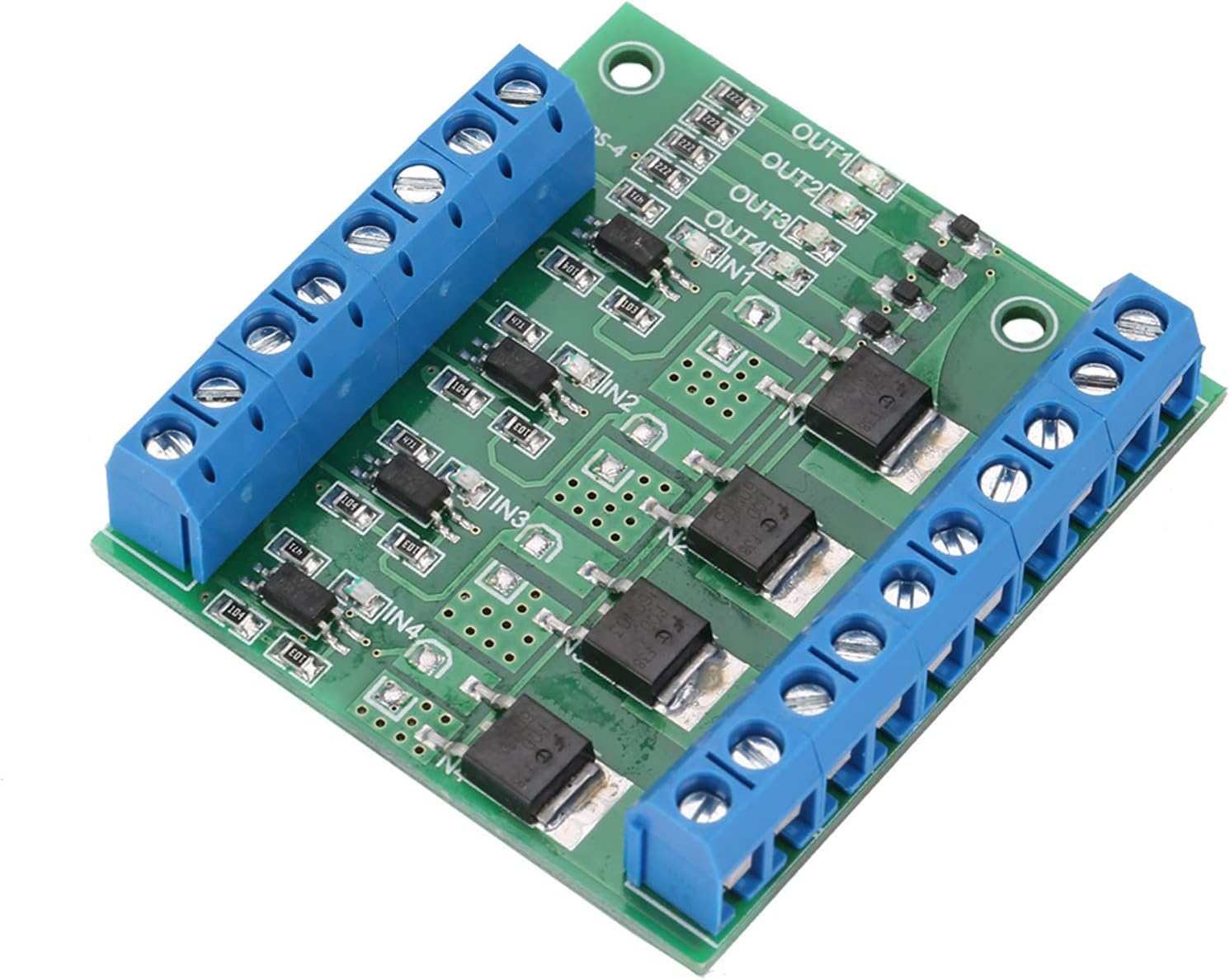
Figure 3.1: Top view of the YYNMOS-4 MOS Tube Module.

Figure 3.2: Angled view of the YYNMOS-4 module.
3.1 Key Features
- Optocoupler Isolation: Provides strong anti-interference ability and ensures safety by isolating input and output signals.
- Signal Indicators: Onboard LEDs for each channel allow for easy monitoring of input/output signal status.
- Screw Terminal Blocks: Facilitates quick, secure, and efficient wiring.
- Wide Application: Capable of controlling various high-power DC equipment.
4. Specifications
| Parameter | Value |
|---|---|
| Model | YYNMOS-4 |
| Input Signal | 3~20V PWM signal |
| PWM Frequency | 0~1kHz |
| Output Capacity | DC 3.7V~27V, current of each channel ≤ 10A |
| Weight (approx.) | 27g |

Figure 4.1: Module Dimensions.
5. Setup and Wiring
Proper wiring is crucial for the safe and effective operation of the YYNMOS-4 module. Refer to the terminal descriptions and wiring diagram below.
5.1 Wiring Terminal Description
- DC+: DC power supply positive terminal.
- DC-: DC power supply negative terminal.
- PWM: Signal input terminal. Connect to a single-chip IO port, PLC interface, or DC power supply for control.
- GND: Signal negative terminal (common ground for input signal).
- OUT+: Output positive terminal. Connect to the positive terminal of the device being controlled.
- OUT-: Output negative terminal. Connect to the negative terminal of the device being controlled.
5.2 Wiring Diagram

Figure 5.1: YYNMOS-4 Wiring Diagram.
- Connect the input signal (PWM) from your controller (e.g., microcontroller IO port, PLC) to the corresponding PWM terminal on the module. Connect the ground of your controller to the GND terminal.
- Connect the DC power supply for the load to the DC+ and DC- terminals. Ensure the voltage is within the specified output capacity (3.7V-27V).
- Connect the device you wish to control (e.g., LED strip, motor) to the OUT+ and OUT- terminals for the desired channel. For example, connect the positive lead of your LED strip to OUT1+ and the negative lead to OUT1-.
- Repeat for additional channels as needed.
6. Operating Instructions
Once wired correctly, the YYNMOS-4 module operates by receiving a PWM signal at its input terminals. This signal controls the switching of the MOS tube, thereby regulating the power delivered to the connected load.
- Apply the appropriate PWM signal (3-20V, 0-1kHz) to the PWM input terminal of the desired channel.
- The onboard signal indicator LED for that channel will illuminate when an active signal is detected.
- The connected load will respond according to the duty cycle of the PWM signal. For example, a higher duty cycle will result in more power delivered to the load.
- Ensure the load's current draw does not exceed 10A per channel to prevent damage.
7. Maintenance
The YYNMOS-4 module is designed for durability and requires minimal maintenance.
- Keep the module clean and free from dust and debris. Use a soft, dry cloth for cleaning.
- Periodically check all wiring connections to ensure they are secure and free from corrosion.
- Avoid exposing the module to excessive heat or direct sunlight.
8. Troubleshooting
- No output from a channel:
- Check if the input PWM signal is present and within the 3-20V range.
- Verify that the signal indicator LED for that channel is illuminated.
- Ensure the load's power supply (DC+ and DC-) is correctly connected and providing the correct voltage.
- Check the load itself to ensure it is functioning correctly and not drawing excessive current.
- Module overheating:
- The load current may be too high. Ensure it does not exceed 10A per channel.
- Ensure adequate ventilation around the module.
- Intermittent operation:
- Check for loose wiring connections.
- Ensure the input PWM signal is stable and free from noise.
9. Warranty and Support
This CHICIRIS product is covered by a manufacturer warranty for 90 days from the date of purchase.
For technical support, warranty claims, or further inquiries, please contact CHICIRIS customer service through the retailer where the product was purchased. Please provide your purchase details and a clear description of the issue.