
1. Introduction
The SolarEpic TEP6425 is a 60A Maximum Power Point Tracking (MPPT) solar charge controller designed for advanced solar power systems. It supports 12V, 24V, and 48V battery systems with automatic voltage sensing. Engineered for high-voltage input, it can handle a maximum PV open-circuit voltage of 250V, allowing for longer series strings of solar panels. This design reduces current and enables the use of thinner, more cost-effective wiring, making it suitable for installations where the solar array is distant from the battery bank. The controller efficiently manages power from complex solar panel arrangements with an extended MPPT voltage range up to 180V, ensuring optimal energy harvest even in varying light conditions. It is compatible with various battery types, including lead-acid (AGM, GEL, FLD) and lithium (LFP, NCM) batteries, and offers scalability through parallel operation with up to 5 additional units.
2. Important Safety Information
- Read all instructions and warnings in this manual before installation and operation.
- Ensure all wiring is performed by qualified personnel and complies with local electrical codes.
- Always disconnect the solar array and battery power before installing or adjusting the controller.
- Wear appropriate personal protective equipment, including eye protection, when working with batteries and electrical systems.
- Do not short-circuit battery terminals or PV terminals.
- Ensure proper ventilation around the controller to prevent overheating.
- The controller is designed for indoor use; avoid exposure to direct sunlight, high temperatures, humidity, or corrosive environments.
3. Product Overview
3.1 Key Features
- Advanced MPPT technology with tracking efficiency of ≥99.5%.
- High conversion efficiency of ≥98.5%.
- Supports 12V/24V/48V battery systems (auto-sensing).
- Maximum PV input voltage of 250V DC.
- Rated charging current of 60A.
- Compatible with lead-acid (AGM, GEL, FLD) and lithium (LFP, NCM) batteries.
- Comprehensive electronic protection features.
- LCD display for real-time data and status.
- Optional mobile app control via Bluetooth/WiFi module.
- Parallel operation capability for system expansion (up to 6 units).
3.2 Front Panel and Display
The front panel features an intuitive LCD screen and three buttons for easy navigation and monitoring of system parameters.

Figure 3.2.1: Intuitive Button Control. This image highlights the LCD screen and the three control buttons (Back, Select, Set/Enter) on the front of the TEP6425 MPPT charge controller, used for navigating menus and adjusting settings.
3.3 Connection Ports
The bottom and side panels of the controller provide various terminals and ports for system connections.

Figure 3.3.1: Appearance Design Details. This diagram illustrates the various connection points on the TEP6425 controller, including PV terminals, battery terminals, grounding terminal, COM port (RJ45), RTS/BMS/CAN COM interface, and the cooling fan.
- PV terminals: Connect to the solar panel array.
- Battery terminals: Connect to the battery bank.
- Grounding terminal: For system grounding.
- COM port (RJ45): For communication with external devices (e.g., PC, remote meter).
- RTS/BMS/CAN COM interface: For Remote Temperature Sensor, Battery Management System, or CAN communication.
- Cooling fan: Ensures proper heat dissipation.
4. Specifications
4.1 Technical Data
| Parameter | Value |
|---|---|
| Brand | SolarEpic |
| Model | TEP6425 |
| Supported System Voltage | 12V / 24V / 48V (Auto-sensing) |
| Max. PV Input Voltage | 250V DC |
| Rated Charging Current | 60A |
| Rated Charging Power (12V) | 780W |
| Rated Charging Power (24V) | 1560W |
| Rated Charging Power (48V) | 3120W |
| Applicable Battery Type | Lead-Acid (AGM, GEL, FLD), Lithium (LFP, NCM) |
| Material | Metal |
| Color | White |
| Item Weight | 9.8 pounds (4.47 kg) |
| Display Type | Digital |
| Manufacturer | Huizhou EPEVER Technology Co.,Ltd. |

Figure 4.1.1: Key Specifications Overview. This image visually summarizes the main technical specifications of the TEP6425 controller, including its voltage compatibility, maximum PV input, charging current, and supported battery chemistries.
4.2 Dimensions
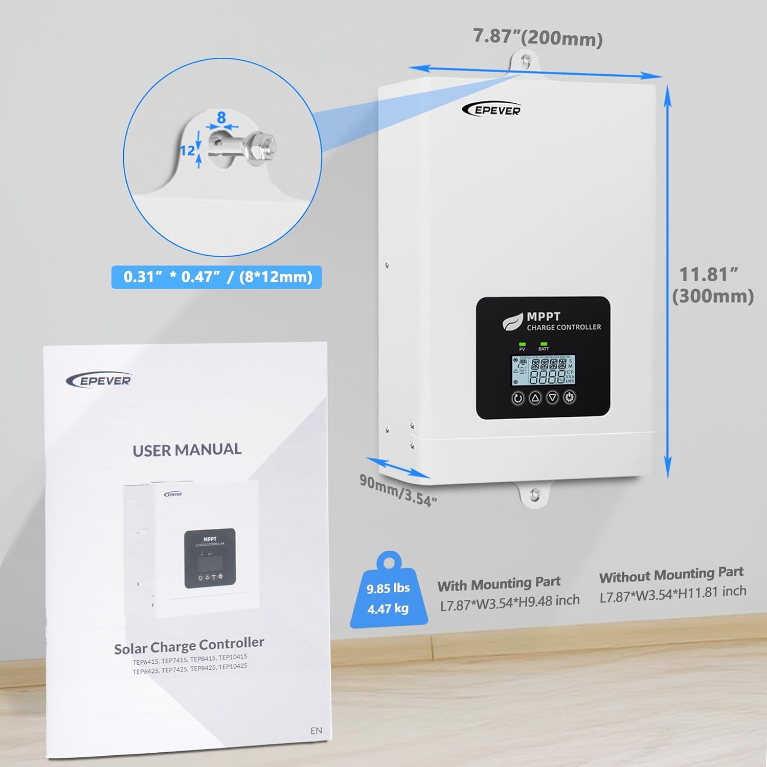
Figure 4.2.1: Dimensions and Weight. This image provides the physical dimensions of the TEP6425 controller (width, height, depth) and its weight, along with details for mounting hardware.
5. Setup and Installation
5.1 Mounting the Controller
- Choose a well-ventilated, dry, and dust-free indoor location.
- Mount the controller vertically on a wall or suitable surface, ensuring adequate clearance (at least 150mm) above and below for proper airflow and cooling.
- Avoid mounting in direct sunlight or near heat sources.
5.2 Wiring Connections
Follow the wiring sequence carefully to prevent damage to the controller or other components. Always connect the battery first, then the solar panels.

Figure 5.2.1: How to Connect. This diagram illustrates the proper connection sequence for the TEP6425 controller within a solar power system, emphasizing the importance of correct wire gauge (recommended 35mm² or 2AWG) and the mandatory installation of a fast-acting fuse (1.25-2 times rated current) on the battery side.
- Connect the Battery: Connect the battery cables to the battery terminals on the controller. Ensure correct polarity (positive to positive, negative to negative).
- Install Battery Fuse: A fast-acting fuse (1.25-2 times the rated current) must be installed on the battery side, close to the battery.
- Connect the Solar Panels: Connect the PV array cables to the PV terminals on the controller. Ensure correct polarity. Verify that the PV open-circuit voltage does not exceed 250V.
- Connect Grounding: Connect the grounding terminal to an earth ground.
- Optional Connections: Connect any optional accessories such as a remote temperature sensor, communication modules (Bluetooth/WiFi), or a remote meter to their respective ports.
5.3 Battery Compatibility
The TEP6425 controller is compatible with a wide range of battery types, automatically detecting 12V, 24V, or 48V systems.

Figure 5.3.1: Compatibility with Various Battery Types. This image demonstrates the TEP6425 controller's versatility, showing its compatibility with common battery types such as LiFePO4, AGM, GEL, and NCM, and its auto-sensing feature for 12V, 24V, or 48V systems.
- Lead-Acid Batteries: Supports Sealed (AGM), Gel, and Flooded (FLD) types.
- Lithium Batteries: Compatible with Lithium Iron Phosphate (LiFePO4) and Nickel Manganese Cobalt (NCM) batteries, often requiring BMS communication for optimal performance.
6. Operating Instructions
6.1 Initial Power-Up
After all connections are securely made, the controller will power on automatically. The LCD display will show system information, and the indicators will light up according to the system status.
6.2 LCD Display Navigation
Use the three buttons on the front panel to navigate through the display menus and view various operating parameters, historical data, and alarm statuses.

Figure 6.2.1: Effortless Monitor. This image provides a detailed view of the TEP6425's LCD screen, illustrating how it displays battery type, system status (solar, battery, load), real-time data, and alarm notifications for easy monitoring.
6.3 Mobile App Control (Optional)
For enhanced monitoring and control, the TEP6425 supports an optional mobile app. This requires a separate Epever Bluetooth or WiFi module (not included) to be connected to the controller's communication port.

Figure 6.3.1: Complete Control Via Mobile App. This image demonstrates the optional mobile app functionality, showing how users can monitor and adjust controller settings remotely via a smartphone after connecting an Epever Bluetooth or WiFi module.
- Real-Time Monitoring: View current system status, voltage, current, and power data.
- Remote Parameter Setting: Adjust charging parameters and other settings from your mobile device.
- Historical Data & Energy Reports: Access past performance data and energy generation reports.
7. Maintenance
Regular maintenance ensures the longevity and optimal performance of your solar charge controller.
- Visual Inspection: Periodically check for any loose connections, damaged wiring, or signs of corrosion.
- Cleanliness: Keep the controller clean and free from dust and debris. Ensure the cooling fan and vents are unobstructed.
- Terminal Check: Ensure all terminal screws are tightened securely. Loose connections can cause overheating and damage.
- Battery Health: Monitor battery voltage and health regularly, especially for lead-acid batteries, to ensure they are being charged correctly.
- Firmware Updates: Check the manufacturer's website for any available firmware updates for improved performance or new features.
8. Troubleshooting
This section provides guidance on common issues you might encounter with your TEP6425 controller.
8.1 Common Issues
- No Display/No Power: Check battery connections and voltage. Ensure the battery is charged above the minimum operating voltage.
- No Charging: Verify PV array connections and voltage. Check for shading on solar panels. Ensure the PV input voltage is within the controller's operating range.
- Low Charging Current: Check PV array size and condition. Ensure proper wire gauge is used for all connections.
- Overheating: Ensure adequate ventilation around the controller. Check if the cooling fan is operating correctly.
- Error Codes: Refer to the specific error codes displayed on the LCD (if any) and consult the full manual or manufacturer's support for detailed solutions.
8.2 Protection Features
The TEP6425 controller includes robust protection features to safeguard your solar investment.

Figure 8.2.1: All-Round Protection. This image highlights the various built-in safety mechanisms of the TEP6425 controller, such as protection against over-temperature, battery undervoltage, PV reverse polarity, overload, short circuits, and battery overvoltage, ensuring system reliability.
- PV Reverse Polarity Protection: Protects against incorrect PV wiring.
- Battery Reverse Polarity Protection: Protects against incorrect battery wiring.
- Battery Overvoltage Protection: Prevents battery overcharging.
- Battery Undervoltage Protection: Prevents battery over-discharging.
- Overload Protection: Protects against excessive current draw from the load.
- Short Circuit Protection: Protects against short circuits in the load or PV array.
- Over Temperature Protection: Shuts down or reduces power if the controller overheats.
- PV Night Anti Backcharging: Prevents current flow from the battery to the solar panels at night.
9. Warranty and Support
9.1 Warranty Information
The SolarEpic TEP6425 MPPT Solar Charge Controller comes with a standard manufacturer's warranty. Please refer to the warranty card included with your product or visit the SolarEpic official website for detailed terms and conditions regarding warranty coverage, duration, and claims procedures.
9.2 Customer Support
For technical assistance, troubleshooting, or any questions regarding your SolarEpic TEP6425 controller, please contact SolarEpic customer support. Have your product model number (TEP6425) and purchase information ready when contacting support.
You can typically find contact information on the SolarEpic website or in the documentation provided with your product.