1. Product Overview
This manual provides essential information for the installation, operation, and maintenance of your YEJMKJ Nema 17 Stepper Motor with T8 Lead Screw. This motor is designed for applications requiring precise positional control, such as 3D printers, CNC machines, and engraving equipment.
1.1. Key Features
- Standard Step Angle: 1.8 degrees (200 steps per revolution) for high precision and smooth motion.
- High Torque: Delivers 0.4Nm (56.64oz.in) holding torque for reliable performance.
- Integrated Lead Screw: Features a 150mm T8 lead screw for linear motion applications.
- Bipolar Design: 2-phase, 4-lead configuration for versatile control.

Figure 1: YEJMKJ Nema 17 Stepper Motor with T8 Lead Screw (150mm variant).
1.2. What's in the Box
The package includes the following components:
- 1 x 42MM Nema 17 Lead Screw Stepper Motor
- 1 x Brass Nut
- 1 x 1m Wiring Harness for Connectors
2. Specifications
Refer to the table below for detailed technical specifications of the YEJMKJ Nema 17 Stepper Motor (SG150mm model).
| Parameter | Value |
|---|---|
| Body Length | 42mm (1.67 inch) |
| Step Angle | 1.8 degrees |
| Phase | 2 |
| Rated Current | 1.7A |
| Shaft Diameter | Φ 10mm |
| Shaft Length (Lead Screw) | 150mm (5.91 inch) |
| Running Speed | 1000 RPM (max) |
| Phase Resistance | 1.8Ω |
| Phase Inductance | 4.2mH |
| Holding Torque | 0.4Nm (56.64oz.in) |
| Rotor Inertia | 57g.cm² |
| Weight | 291g (12.3 ounces) |
| Product Dimensions (Motor Body) | 1.65 x 1.65 x 1.57 inches (42 x 42 x 40mm) |
| UPC | 747607586628 |
| Model Number | SG150mm |

Figure 2: Detailed electrical and mechanical parameters.

Figure 3: Product dimensions and wiring schematic.
3. Setup and Installation
Proper installation is crucial for optimal performance and longevity of your stepper motor. Follow these steps carefully.
3.1. Mounting the Motor
- Identify the mounting holes on the front face of the motor. These are typically M3 threaded holes.
- Secure the motor to your desired mounting surface (e.g., 3D printer frame, CNC gantry) using appropriate M3 screws. Ensure the motor is firmly attached to prevent vibration and misalignment.
- Ensure the lead screw is aligned with the linear guide mechanism of your application. The brass nut should engage smoothly with the lead screw.
3.2. Wiring the Motor
The YEJMKJ Nema 17 stepper motor is a 2-phase, 4-lead bipolar motor. It comes with a 1m wiring harness. Connect the motor to your stepper motor driver according to the following color code. Note: It is recommended to verify the wiring against the motor's internal coil configuration if issues arise, as some wiring harnesses may have reversed connections for specific colors.
- Red: A+
- Blue: A-
- Green: B+
- Black: B-
Refer to Figure 3 for the electrical schematic and excitation sequence. If the motor rotates in the incorrect direction, you may need to reverse the connections for one coil (e.g., swap A+ and A- or B+ and B-).
Video 1: Overview of the Nema 17 Stepper Motor with T8 Lead Screw, demonstrating its physical characteristics and rotation.
4. Operating Instructions
Stepper motors operate by converting digital pulses into precise mechanical rotational steps. The integrated lead screw translates this rotation into linear motion.
4.1. Basic Operation Principles
- Step Angle: This motor has a 1.8-degree step angle, meaning 200 full steps complete one full revolution (360 degrees / 1.8 degrees = 200 steps).
- Microstepping: Most stepper motor drivers support microstepping, which divides each full step into smaller increments (e.g., 1/2, 1/4, 1/8, 1/16, 1/32 steps). This results in smoother motion and reduced resonance, though it does not increase the motor's positional accuracy beyond its full step resolution.
- Control Signals: Stepper motors are typically controlled by a step (pulse) signal and a direction signal from a microcontroller or CNC controller. Each pulse causes the motor to move one step (or microstep) in the direction specified by the direction signal.
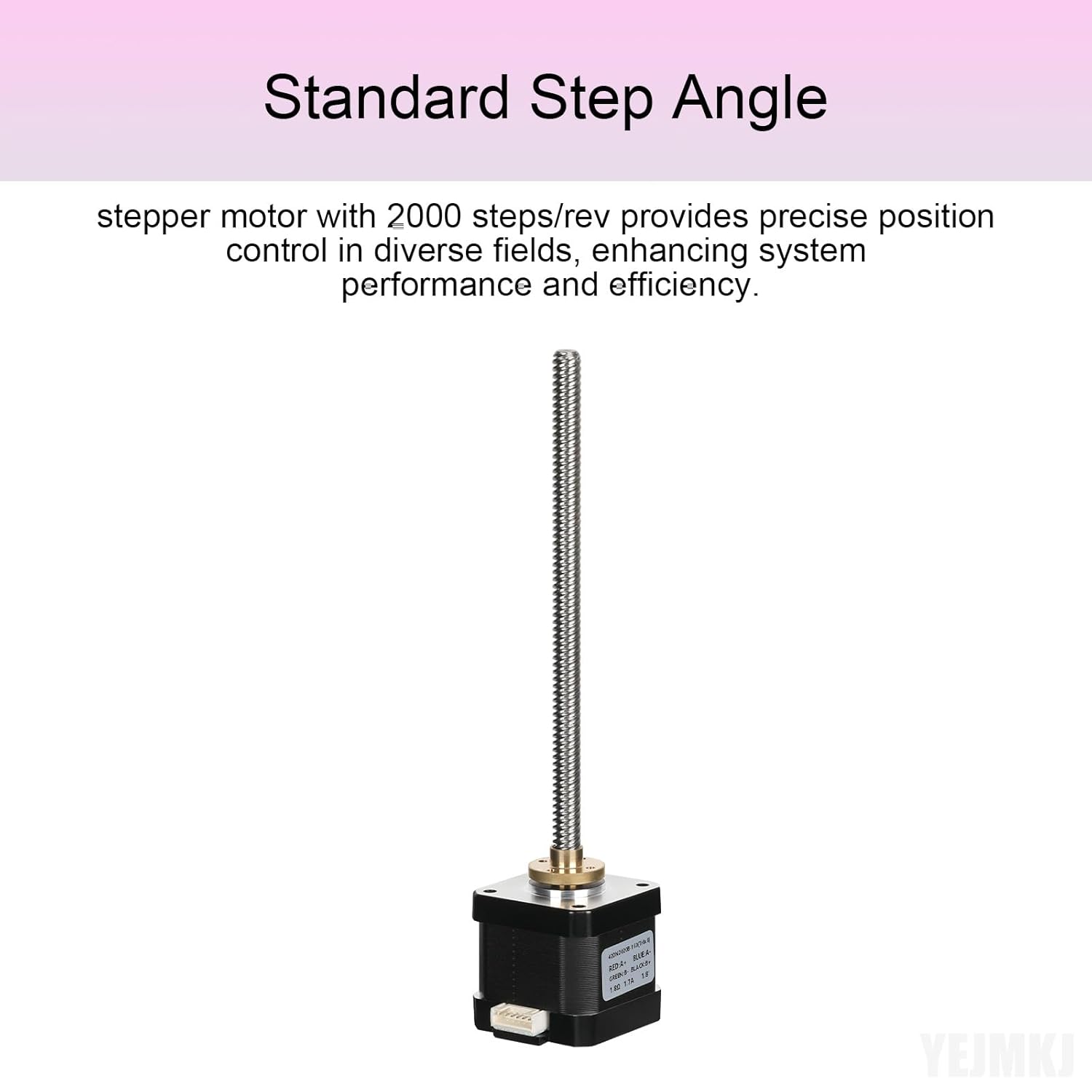
Figure 4: Illustration of the standard step angle for precise control.
4.2. Power Supply and Driver Settings
- Ensure your power supply provides sufficient voltage and current for the motor and driver. The rated current for this motor is 1.7A per phase.
- Configure your stepper motor driver's current limit to match or slightly exceed the motor's rated current (1.7A) to achieve optimal torque without overheating.
- Set the microstepping resolution on your driver according to your application's requirements for smoothness and speed.
5. Maintenance
Regular maintenance helps ensure the long-term reliability and performance of your stepper motor and lead screw assembly.
- Lead Screw Lubrication: Periodically apply a thin layer of appropriate lubricant (e.g., lithium grease or PTFE-based lubricant) to the T8 lead screw. This reduces friction, wear, and noise, and improves the smoothness of linear motion.
- Cleaning: Keep the motor and lead screw free from dust, debris, and foreign particles. Use a soft, dry cloth or compressed air for cleaning. Avoid using harsh chemicals that could damage the motor's components.
- Connection Check: Periodically inspect all electrical connections for tightness and signs of wear or corrosion. Loose connections can lead to intermittent operation or motor damage.
- Temperature Monitoring: Ensure the motor operates within its recommended temperature range. Excessive heat can reduce motor lifespan. If the motor becomes excessively hot, check driver current settings and consider adding heat sinks or active cooling.
6. Troubleshooting
If you encounter issues with your YEJMKJ Nema 17 Stepper Motor, refer to the following troubleshooting guide.
6.1. Motor Not Moving or Stalling
- Power Supply: Verify that the power supply is providing the correct voltage and sufficient current to the stepper motor driver.
- Wiring: Double-check all wiring connections between the motor, driver, and controller. Ensure no wires are loose or incorrectly connected. Refer to Figure 3 and Section 3.2 for correct wiring.
- Driver Current: Confirm that the stepper motor driver's current limit is set appropriately for the motor (1.7A). Too low a current will result in insufficient torque.
- Step Pulses: Ensure the controller is sending step pulses to the driver. Check your control software or firmware settings.
- Overload: The load on the lead screw might be too high. Reduce the load or consider a motor with higher torque if the application demands it.
6.2. Incorrect Rotation Direction
- Wiring: If the motor rotates in the opposite direction, reverse the connections of one coil. For example, swap the Red (A+) and Blue (A-) wires, or swap the Green (B+) and Black (B-) wires. Do not swap wires between different coils.
- Software/Firmware: Many control systems allow reversing the motor direction in software or firmware settings. Consult your controller's documentation.
6.3. Excessive Noise or Vibration
- Microstepping: Increase the microstepping resolution on your stepper motor driver. Higher microstepping (e.g., 1/16 or 1/32) generally leads to smoother and quieter operation.
- Driver Tuning: Some advanced stepper drivers offer tuning features (e.g., decay mode, resonance suppression). Refer to your driver's manual for optimization.
- Mounting: Ensure the motor is securely mounted and there is no resonance with the mounting surface.
- Lead Screw Condition: Check the lead screw for any binding, damage, or lack of lubrication. Lubricate as per Section 5.
7. Warranty and Support
YEJMKJ products are manufactured to high-quality standards. For any concerns or questions during the purchasing process or product usage, please feel free to contact us. We are committed to providing prompt assistance and support.
Please retain your proof of purchase for any warranty claims. Specific warranty terms and conditions may apply and are available upon request or through the retailer where the product was purchased.
For further assistance, visit the YEJMKJ Store on Amazon.