1. Introduction
This manual provides detailed instructions for the installation, configuration, and operation of the eletechsup Multifunction Modbus RTU Relay Module. This module is designed for industrial control and home automation applications, offering a versatile solution for PLC IO expansion, data acquisition, and relay control via RS485 communication.
The module features 4-channel 10A relay outputs, 2 analog inputs (4-20mA and 0-10V), and 2 digital inputs (NPN/PNP compatible). It supports standard Modbus RTU commands for reliable communication.
2. Safety Information
- Ensure the power supply voltage matches the module's specified voltage (12V DC for this model). Incorrect voltage can damage the device.
- Disconnect power before making any wiring connections or disconnections.
- Avoid touching exposed electrical components while the module is powered.
- Install the module in a dry, well-ventilated area, away from direct sunlight, high temperatures, and corrosive gases.
- The module is equipped with TVS anti-surge protection; however, proper grounding and surge protection for the entire system are recommended.
3. Product Overview
3.1 Features
- DC 12V power supply (12V Version).
- Low standby current (12mA with all relays closed).
- Inputs: 1-channel 0-20mA current analog input, 1-channel 0-10V voltage analog input, 1-channel 0-24V voltage analog input, 2-channel photoelectric isolation switch input (NPN/PNP compatible).
- Outputs: 4-channel 10A relay switch output.
- Supports standard Modbus RTU commands (function codes: write 05/06/15/16, read 01/02/03/04).
- Hardware Reset function and TVS anti-surge protection.
- Supports up to 64 devices in parallel under Modbus command mode.
- Configurable baud rates: 2400, 4800, 9600 (default), 19200, 38400, 57600, 115200BPS.
- Configurable parity: None, Even, Odd.
- Adjustable data sending and returning time (maximum 1000ms).
3.2 Components
The module consists of a PCB board with terminal blocks for power, inputs, outputs, and RS485 communication. It includes four relays, an MCU, and various passive components.
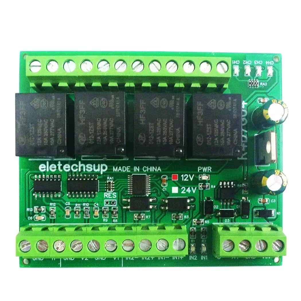
Figure 1: Top view of the eletechsup Multifunction Modbus RTU Relay Module (12V only Board).

Figure 2: Bottom view of the PCB, showing the 'eletechsup' branding and power selection jumpers.
3.3 Applications
- PLC IO expansion board
- Smart Home and Home Automation systems
- Security Monitoring and Identification systems
- PTC Camera and IP Camera control
- LED Lamp Drivers
- Automatic curtain control
4. Setup
4.1 Power Supply Connection
Connect a stable DC 12V power supply to the designated power terminals on the module. Ensure correct polarity (positive to +V, negative to GND).
4.2 Wiring Diagram
Refer to the following diagrams for proper wiring of inputs, outputs, and RS485 communication.

Figure 3: Detailed wiring diagram for the module, illustrating connections for current, voltage, digital inputs, relay outputs, RS485, and DC 12V/24V power. Note: This specific model is 12V only.

Figure 4: Close-up view of the input and output terminal labels, including 0-20mA current input, 0-24V voltage input, 0-10V voltage input, 2-channel NPN/PNP digital input, and 4-channel 10A relay switch outputs (COM, NO, NC).
4.2.1 Analog Inputs
- 0-20mA Current Input: Connect the current source to the designated 0-20MA input terminals.
- 0-10V Voltage Input: Connect the voltage source to the designated 0-10V input terminals.
- 0-24V Voltage Input: Connect the voltage source to the designated 0-24V input terminals.
4.2.2 Digital Inputs
The module provides 2-channel photoelectric isolation switch inputs, compatible with both NPN and PNP sensors. Connect your digital input signals to the IN1 and IN2 terminals.
4.2.3 Relay Outputs
Each of the 4 relay channels provides Common (COM), Normally Open (NO), and Normally Closed (NC) contacts. Connect your load to the appropriate terminals based on your application's requirements.
4.2.4 RS485 Communication
Connect the RS485 A+ and B- terminals of the module to your RS485 master device (e.g., PC via USB-RS485 converter, PLC). Ensure correct polarity for communication.

Figure 5: Example of connecting the module to a PC via a USB to RS485 converter for Modbus communication.
4.3 Modbus RTU Configuration
The module operates as a Modbus RTU slave device. Before operation, configure the following parameters:
- Slave ID: Each module on an RS485 bus must have a unique Slave ID (1 to 64). This can be set via Modbus commands.
- Baud Rate: Default is 9600BPS. Can be changed to 2400, 4800, 19200, 38400, 57600, 115200BPS via Modbus commands.
- Parity: Default is None. Can be changed to Even or Odd via Modbus commands.

Figure 6: Multiple modules connected in parallel on an RS485 bus, each configured with a unique Slave ID.
5. Operating Instructions
The module communicates using standard Modbus RTU protocol. A Modbus master device sends commands to read inputs or control outputs.
5.1 Modbus Function Codes
The module supports the following Modbus function codes:
- Read Coils (01): Read the status of relay outputs.
- Read Discrete Inputs (02): Read the status of digital inputs.
- Read Holding Registers (03): Read analog input values or configuration parameters.
- Read Input Registers (04): Read analog input values.
- Write Single Coil (05): Control a single relay output.
- Write Single Register (06): Write to a single configuration parameter (e.g., baud rate, slave ID).
- Write Multiple Coils (15): Control multiple relay outputs simultaneously.
- Write Multiple Registers (16): Write to multiple configuration parameters.
Refer to the Modbus RTU protocol specification for detailed command structures and register addresses specific to this module. Contact the manufacturer for a detailed register map if not provided.
5.2 Relay Control
Relays can be controlled using Modbus function codes 05 (Write Single Coil) or 15 (Write Multiple Coils). Each relay corresponds to a specific coil address.
5.3 Analog Input Reading
Analog input values (0-20mA, 0-10V, 0-24V) can be read using Modbus function codes 03 (Read Holding Registers) or 04 (Read Input Registers). The module will convert the analog signal into a digital value, typically a 16-bit integer, which can then be scaled by the master device.
5.4 Digital Input Reading
The status of the 2 digital inputs can be read using Modbus function code 02 (Read Discrete Inputs). A value of 1 typically indicates an active input, and 0 indicates an inactive input.
6. Maintenance
6.1 Cleaning
Periodically clean the module with a soft, dry cloth. Do not use liquid cleaners or solvents, as they may damage the components. Ensure the module is powered off before cleaning.
6.2 Environmental Considerations
Ensure the operating environment remains within the specified temperature and humidity ranges. Avoid exposure to excessive dust, moisture, or corrosive substances to prolong the module's lifespan.
7. Troubleshooting
7.1 Communication Issues
- No Response from Module: Check power supply, RS485 wiring (A+/B- polarity), baud rate, parity, and slave ID settings. Ensure the master device is correctly configured.
- Intermittent Communication: Verify RS485 cable integrity, termination resistors (if applicable for long distances), and ensure no other devices on the bus have the same Slave ID.
7.2 Relay Not Activating
- Check the Modbus command sent to ensure the correct function code (05 or 15) and coil address are used.
- Verify the load connected to the relay is within the specified maximum load ratings (10A / 250VAC, 10A / 125VAC, 10A / 30VDC, 10A / 28VDC, 10A / 12VDC).
- Ensure the power supply to the module is stable.
7.3 Incorrect Analog Readings
- Verify the analog sensor is correctly wired and functioning.
- Check the Modbus command for reading analog inputs (function code 03 or 04) and the correct register address.
- Ensure proper scaling is applied on the master device to convert the raw digital value back to the physical unit (mA or V).
7.4 Hardware Reset
The module features a hardware reset function. If the module becomes unresponsive or requires a factory settings reset, locate the RESET jumper on the PCB and follow the manufacturer's instructions for activation. This typically involves shorting the pins momentarily while powered off, then powering on.
8. Specifications
| Parameter | Value |
|---|---|
| Model | Multifunction Modbus RTU Relay Module (12V only Board) |
| Power Supply | DC 12V |
| Standby Current (all relays closed) | 12mA |
| Relay Open Current (1 relay) | 40mA |
| Analog Inputs | 1-channel 0-20mA, 1-channel 0-10V, 1-channel 0-24V |
| Digital Inputs | 2-channel Photoelectric Isolation (NPN/PNP compatible) |
| Relay Outputs | 4-channel 10A Switch Output |
| Maximum Load (Relay) | 10A / 250VAC, 10A / 125VAC, 10A / 30VDC, 10A / 28VDC, 10A / 12VDC |
| Communication Interface | RS485 |
| Communication Protocol | Modbus RTU |
| Baud Rates | 2400, 4800, 9600 (default), 19200, 38400, 57600, 115200BPS |
| Parity | None, Even, Odd |
| Max Parallel Devices | 64 |
| Dimensions (PCB Board) | 88 x 72 x 12mm |
| Weight (PCB Board) | 85g |
9. Warranty and Support
For warranty information and technical support, please refer to the product's purchase documentation or contact the seller directly. Keep your purchase receipt for any warranty claims.