1. Overview
The FNIRSI LC1020E is a handheld LCR meter designed for precise measurement of inductance, capacitance, and resistance. It features a dual-parameter display, allowing simultaneous viewing of main and secondary parameters such as X, D, Q, θ, and ESR. With multiple test frequencies and voltage levels, it provides accurate readings for various electronic components. The device also includes a smart sorting function for efficient component screening.
2. Safety Information
Please read and understand all safety instructions before operating the device. Failure to follow these instructions may result in electric shock, fire, or damage to the device.
- Do not attempt to measure live circuits or components with stored energy (e.g., charged capacitors) without first discharging them.
- Ensure the test leads are in good condition and properly connected before making measurements.
- Do not operate the device in wet environments or with wet hands.
- Avoid exposing the device to extreme temperatures, direct sunlight, or strong vibrations.
- Only use the specified power adapter or batteries if applicable.
- Refer all servicing to qualified personnel.
3. Setup
3.1 Powering the Device
The LC1020E is typically powered by an internal rechargeable battery or an external power source. Ensure the device is sufficiently charged before use. Connect the appropriate power adapter if external power is required.
3.2 Connecting Test Leads
Connect the provided test leads to the input terminals on the LCR meter. Ensure a secure connection to prevent inaccurate readings or damage.

Image: The FNIRSI LC1020E LCR Meter with test leads connected to a large capacitor, demonstrating the primary and secondary parameter display.
4. Operating Instructions
4.1 Power On/Off
Press and hold the Power button to turn the device on or off.
4.2 Basic Navigation
The LC1020E features several buttons for navigation and setting adjustments:
- AUTO/R/L/C/Z: Switches between automatic component recognition and manual selection of Resistance, Inductance, Capacitance, or Impedance measurement modes.
- X/D/Q/θ/ESR: Toggles the secondary parameter displayed (Reactance, Dissipation Factor, Quality Factor, Phase Angle, Equivalent Series Resistance).
- OK: Confirms selections or enters sub-menus.
- HOLD: Freezes the current measurement on the display.
- SPEED: Adjusts the measurement speed (Fast, Medium, Slow).
- RANGE: Manually selects the measurement range.
- FREQ: Selects the test frequency.
- LEVEL: Adjusts the test voltage level.
- OFFSET: Used for calibration or bias settings.
5. Measurement Modes and Parameters
5.1 Auto Measurement
In AUTO mode, the LC1020E automatically identifies the component type (Resistor, Inductor, or Capacitor) and switches to the appropriate measurement mode, simplifying testing.

Image: The FNIRSI LC1020E LCR Meter in 'AUTO' mode, displaying capacitance and dissipation factor for a component, with illustrations of an inductor, resistor, and capacitor.
5.2 Dual Parameter Display
The device simultaneously displays a primary parameter (L, C, R) and a secondary parameter (X, D, Q, θ, ESR), providing a comprehensive analysis of the component under test.
5.3 Test Frequencies and Voltage Levels
The LC1020E offers multiple test frequencies and RMS voltage levels for versatile measurements:
- Frequencies: 100Hz, 120Hz, 1kHz, 10kHz, 100kHz
- RMS Voltage Levels: 0.1V, 0.3V, 0.6V
- Internal Bias: 0.0V, 0.5V

Image: The FNIRSI LC1020E LCR Meter display illustrating the selectable test frequencies (100Hz, 120Hz, 1kHz, 10kHz, 100kHz) and RMS voltage levels (0.1V, 0.3V, 0.6V).
5.4 Practical Measurement Scenarios
The LC1020E can be used for various component measurements:
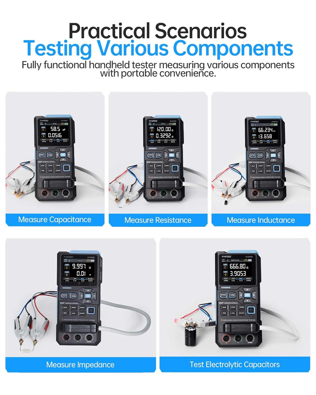
Image: A collage of five images showing the FNIRSI LC1020E LCR Meter measuring different components: capacitance, resistance, inductance, impedance, and electrolytic capacitors.
6. Smart Sorting & Comparison Mode
The smart sorting feature allows for efficient screening of components based on preset nominal values and tolerance limits. This mode calculates the relative error (%) and provides alerts via sound or LED if components fall outside the specified range.
6.1 Setting Nominal and Tolerance
- Navigate to the Sorting/Comparison mode in the menu.
- Set the desired nominal value for the component (e.g., 100nF for a capacitor).
- Define the tolerance percentage (0.1% to 99.9%).
6.2 Performing Sorting
Once settings are configured, test components. The device will indicate whether the component meets the criteria (Pass/Fail) and track success/fail counts.

Image: The FNIRSI LC1020E LCR Meter demonstrating its sorting and comparison mode, showing a component passing the test and another failing, with various components laid out.
7. Calibration
For optimal accuracy, perform open/short calibration periodically or when changing test leads. This compensates for stray capacitance and inductance in the test setup.
7.1 Open Calibration
With no component connected to the test leads, initiate the open calibration process from the menu. This measures and compensates for stray capacitance.
7.2 Short Calibration
Short the test leads together (connect positive to negative) and initiate the short calibration. This measures and compensates for residual inductance and resistance in the leads.
8. FNIRSI LCR-ST1 Tweezer Tester
The FNIRSI LCR-ST1 is a portable LCR/ESR meter in a tweezer format, designed for precise measurement of surface-mount devices (SMD) and other small components. It supports resistance, capacitance, inductance, and diode measurements.

Image: The FNIRSI LCR-ST1 Smart Tweezer LCR/ESR Meter being used to test a component on a circuit board, highlighting its compact design and measurement capabilities.
8.1 LCR-ST1 Measurement Capabilities
- Test Frequencies: 100 Hz, 1 kHz, 10 kHz
- Test Voltage: 0.3 Vrms, 0.6 Vrms
- Parameters Measured: R, C, L, Diodes, D Value (Dissipation Factor), Q Value (Quality Factor), X Value (Reactance), Z Value (Total Impedance), ESR (Equivalent Series Resistance).

Image: The FNIRSI LCR-ST1 Smart Tweezer displaying its auto-recognition feature and various parameters like D, Z, Q, X, and ESR, while testing small components.
8.2 Precision Measurement
The LCR-ST1 offers high precision with minimum measurements down to 10mΩ, 1µH, and 1pF, with an accuracy range between 0.5% and 5%.

Image: A close-up of the FNIRSI LCR-ST1 Smart Tweezer display, showing a precision resistance measurement of 1.942 Ω and a dissipation factor (D) of 458.70.
9. Specifications
| Feature | Specification |
|---|---|
| Display Count | 19,999 |
| Test Frequencies | 100Hz, 120Hz, 1kHz, 10kHz, 100kHz |
| Test Voltage Levels | 0.1V, 0.3V, 0.6V |
| Internal Bias | 0.0V, 0.5V |
| Capacitance Range | 1pF – 100mF |
| Resistance Range | 10mΩ – 10MΩ |
| Inductance Range | 1µH – 100H |
| Output Impedance | 100Ω |
| Measurement Speed | Fast (4/s), Medium (2/s), Slow (1/s) |
| LCR-ST1 Test Frequencies | 100 Hz, 1 kHz, 10 kHz |
| LCR-ST1 Test Voltage | 0.3 Vrms, 0.6 Vrms |
| LCR-ST1 Resistance Range | 10 mΩ to 10 MΩ |
| LCR-ST1 Capacitance Range | 1 pF to 22 mF |
| LCR-ST1 Inductance Range | 1 µH to 10 H |
10. Troubleshooting
10.1 Inaccurate Readings
- Ensure test leads are properly connected and not damaged.
- Perform open/short calibration.
- Check if the correct measurement mode and frequency are selected for the component.
- Ensure the component is fully discharged before testing.
10.2 Device Not Powering On
- Verify the battery is charged or the external power adapter is connected and functioning.
- Check for any physical damage to the device or power port.
10.3 Display Issues
- If the display is blank or flickering, try restarting the device.
- Ensure the device is not exposed to extreme temperatures.
11. Warranty & Support
11.1 Warranty Information
This product typically comes with a standard return policy, allowing for refunds or replacements within 30 days of purchase. Please refer to your purchase documentation for specific warranty terms and conditions.
11.2 Customer Support
For technical assistance, troubleshooting, or warranty claims, please contact FNIRSI customer support or visit the official FNIRSI store online. You can find more information and contact details at the FNIRSI Technology Store.


