1. Introduction
This manual provides detailed instructions for the safe and effective operation, setup, and maintenance of your TOOLTOP Awithz HD2 Battery Spot Welder. Please read this manual thoroughly before using the device to ensure proper function and to prevent damage or injury. This spot welder is designed for welding nickel sheets onto 18650 battery cells and similar applications.

Image 1.1: The Awithz HD2 Battery Spot Welder being used to weld battery cells.
2. Safety Precautions
WARNING: Improper use of this device can result in serious injury or damage to property. Always follow safety guidelines.
- Always wear appropriate personal protective equipment (PPE), including safety glasses, when operating the spot welder.
- Ensure the work area is well-ventilated and free from flammable materials.
- Do not touch the welding pins or the workpiece immediately after welding, as they may be hot.
- Keep the device away from water and moisture. Do not operate in wet conditions.
- Do not attempt to weld materials other than those specified (e.g., nickel sheets, copper sheets up to specified thickness).
- Keep out of reach of children.
- Do not disassemble or modify the device. Refer all servicing to qualified personnel.
- Ensure batteries being welded are not damaged or leaking.
3. Package Contents
Verify that all items listed below are present in your package:
- 1 x TOOLTOP Awithz HD2 Battery Spot Welder
- 1 x 2M Nickel Roll
- 1 x Sandpaper
- 1 x Type-C Charging Cable
- 2 x Spare Welding Needles (Alumina Copper Solder Pins)

Image 3.1: Included accessories with the Awithz HD2 Battery Spot Welder.
4. Product Features
The Awithz HD2 Battery Spot Welder incorporates several advanced features for efficient and precise welding:
- Weldable Thickness: Capable of welding up to 0.2mm (MAX) nickel sheet and 0.15mm copper sheet.
- Adjustable Gears: Features 90 levels of power adjustment for precise control over welding strength.
- High-Definition Digital Display: Provides real-time information on battery level, gear setting, preheat time, trigger time, and temperature.
- Detachable & Replaceable Pins: Alumina copper solder pins are detachable and replaceable, with adjustable spacing for versatility.
- High-Magnification A-Grade Battery Cells: Utilizes quality battery cells for extended machine life and stable power supply.
- Automatic and Manual Modes: Offers flexibility in operation.
- Ergonomic Design: Engineered for comfortable handheld use.
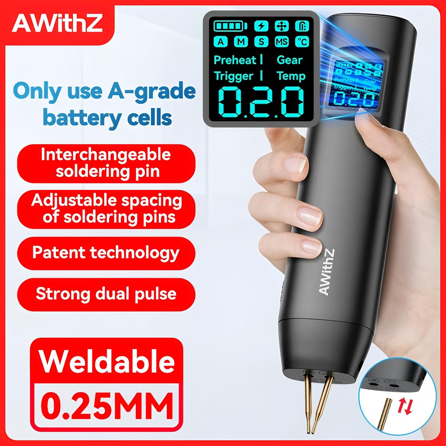
Image 4.1: Overview of the Awithz HD2's primary features.

Image 4.2: The high-definition digital display and its adjustable settings.

Image 4.3: Illustration of the high-magnification A-grade battery cells.
5. Setup Guide
5.1 Charging the Device
Before first use, fully charge the spot welder using the provided Type-C charging cable and a compatible USB power adapter (not included). The display will indicate charging status.
5.2 Installing/Adjusting Welding Pins
- Ensure the device is powered off.
- Insert the alumina copper solder pins into the designated slots on the device.
- Adjust the spacing of the pins as needed for your specific welding application. Ensure both pins are securely fastened.
- The scientific needle changing design allows for easy and secure pin installation, avoiding issues common with threaded or parallel welding needles.

Image 5.1: Proper installation of welding pins.
6. Operating Instructions
6.1 Powering On/Off
Press and hold the power button to turn the device on or off. The digital display will illuminate upon power-on.
6.2 Adjusting Welding Parameters
Use the control buttons to navigate through the settings on the high-definition digital display. You can adjust:
- Gear (Power Level): Select from 90 levels of power adjustment. Start with lower settings and gradually increase as needed for your material.
- Preheat Time: Adjust the preheating duration for optimal welding results, especially with thicker materials.
- Trigger Time: Set the duration of the welding pulse.
- Mode: Switch between Automatic and Manual welding modes.
6.3 Welding Procedure
- Prepare your workpiece: Ensure the nickel strip and battery terminals are clean and free of oxidation. Use sandpaper if necessary.
- Place the nickel strip firmly against the battery terminal.
- Position the welding pins squarely onto the nickel strip, ensuring both pins make good contact.
- In Automatic Mode, the device will detect contact and automatically trigger the weld after a short delay.
- In Manual Mode, press the trigger button (if available, or apply pressure until weld initiates) to perform the weld.
- After welding, lift the pins straight up to avoid damaging the weld.
- Inspect the weld for strength and consistency. Adjust gear settings if the weld is too weak or too strong.

Image 6.1: Example of welding results on battery cells.
7. Maintenance
7.1 Cleaning
Regularly clean the welding pins and the device casing. Use a dry, soft cloth. Do not use abrasive cleaners or solvents. Ensure no metal dust or debris accumulates around the welding pins.
7.2 Pin Replacement
Over time, the alumina copper solder pins may wear down. Replace them with new pins from the spare set provided or purchase genuine replacements. Refer to Section 5.2 for pin installation instructions.
7.3 Storage
Store the spot welder in a cool, dry place, away from direct sunlight and extreme temperatures. Ensure the device is powered off before storage.
8. Troubleshooting
- No Weld/Weak Weld:
- Check battery charge level. Recharge if low.
- Increase the gear (power) setting.
- Ensure welding pins are clean and making good contact with both the nickel strip and battery.
- Verify the nickel strip and battery terminals are clean.
- Adjust preheat and trigger times. - Overheating:
- Allow the device to cool down. The display shows real-time temperature monitoring.
- Reduce the frequency of welds. - Device Not Powering On:
- Ensure the device is fully charged.
- Check the Type-C charging cable and power adapter. - Inconsistent Welds:
- Ensure consistent pressure is applied to the welding pins.
- Check for worn or damaged welding pins.
- Verify stable power supply from the internal battery.
If problems persist, contact customer support.
9. Technical Specifications
| Specification | Value |
|---|---|
| Model Number | TT-Awithz-HD2 |
| Brand | TOOLTOP |
| Weldable Nickel Sheet Thickness | Up to 0.2mm (MAX) |
| Weldable Copper Sheet Thickness | Up to 0.15mm |
| Power Adjustment Gears | 90 Levels |
| Battery Type | High-magnification A-grade battery cells |
| Charging Port | Type-C |
| Certifications | CE, RoHS |
10. Warranty and Support
This product is manufactured by TOOLTOP. For specific warranty details, please refer to the warranty card included with your purchase or contact the retailer. EU spare part availability duration is 1 year from the date of purchase.
For technical support or inquiries, please contact your point of purchase or visit the official TOOLTOP website for customer service information.


