
1. Introduction
The NJTY T6125 is a digital insulation resistance tester designed for professional electrical measurement applications. This megohmmeter provides a maximum test voltage of 2500V and measures insulation resistance from 0.01MΩ to 200GΩ. It also includes capabilities for measuring AC voltage up to 600V and low resistance values. This manual provides essential information for the safe and effective operation, setup, and maintenance of your NJTY T6125.
2. Safety Information
Read all safety warnings and instructions before using this product. Failure to follow these instructions may result in electric shock, fire, or serious injury.
- Always ensure the equipment under test is de-energized and properly discharged before connecting the tester.
- The NJTY T6125 complies with IEC/EN 61010-1 CAT III 1000V / CAT IV 600V safety standards. Adhere to these ratings.
- Do not use the tester if it appears damaged or if the test leads are compromised.
- Avoid touching the test leads or the circuit under test during measurement, especially when high voltage is applied.
- The device features automatic discharge and high-voltage warnings. Pay attention to these indicators.
- Ensure proper battery installation and replacement. Do not mix old and new batteries or different battery types.
- Do not operate the tester in wet environments or in the presence of explosive gases or dust.
- Only qualified personnel should perform electrical testing.
3. Product Overview
3.1 Key Features
- Wide Insulation Resistance Measurement: 0.01MΩ to 200GΩ with selectable output voltages (250V, 500V, 1000V, 2500V).
- AC Voltage Measurement: 10V to 600V.
- Low Resistance Measurement: 0.01Ω to 60Ω.
- Diagnostic Capabilities: Automatically calculates Dielectric Absorption Ratio (DAR) and Polarization Index (PI).
- Data Hold: Freezes measurement readings for easy recording.
- Over-Range Alarm: Notifies when measurements exceed capacity.
- Automatic Shutdown: Conserves battery life during inactivity.
- Backlit LCD: Large, clear display for various lighting conditions.
- Durable Design: Shockproof, dustproof, and moisture-proof structure with a protective case.
3.2 Package Contents
Verify that all items are present in the package:
- NJTY T6125 Digital Insulation Resistance Tester
- Pair of Silicone Test Leads (Red and Black)
- Pair of Alligator Clips
- Soft-sided Carrying Bag
- Instruction Manual
- 8 x AA Batteries (may be included or sold separately depending on region)

Figure 1: Package contents including the T6125 tester, test leads, alligator clips, carrying bag, and instruction manual.
4. Setup
4.1 Battery Installation
- Ensure the tester is powered off.
- Locate the battery compartment on the back of the device.
- Open the battery compartment cover.
- Insert 8 AA batteries, observing the correct polarity (+/-) as indicated inside the compartment.
- Close the battery compartment cover securely.
The T6125 can also be powered by an external 12V 5A power adapter (not included).
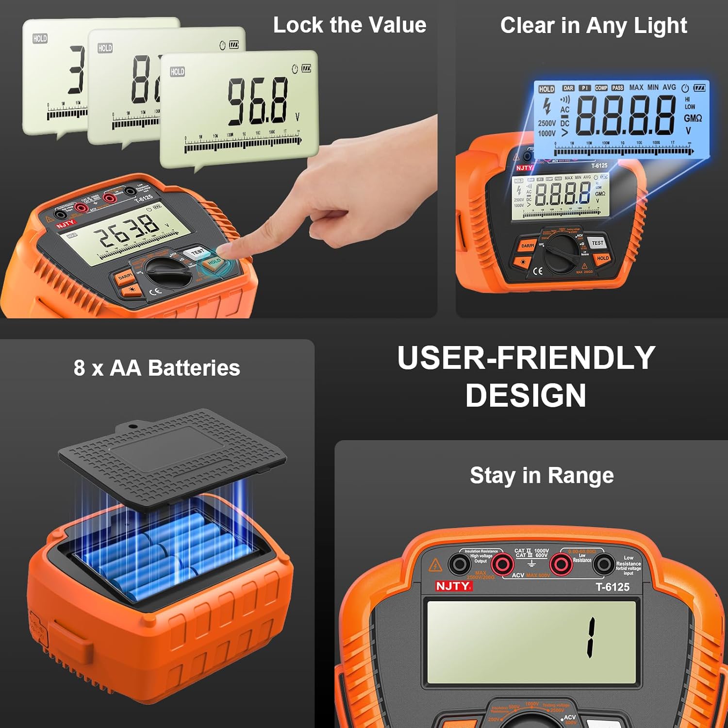
Figure 2: Battery installation for the T6125 tester.
4.2 Connecting Test Leads
- Insert the red test lead into the "VΩ" input jack.
- Insert the black test lead into the "COM" input jack.
- Ensure connections are firm before proceeding with any measurements.
5. Operating Instructions
5.1 Powering On/Off
Rotate the central rotary switch to the desired measurement function to power on the device. To power off, rotate the switch to the "OFF" position. The device features an automatic shutdown function after a period of inactivity to conserve battery life.
5.2 Insulation Resistance Measurement
- Ensure the circuit under test is de-energized and isolated.
- Connect the test leads to the circuit points where insulation resistance is to be measured.
- Rotate the central switch to one of the insulation resistance test voltage settings (250V, 500V, 1000V, or 2500V).
- Press the TEST button to initiate the measurement. The high voltage warning indicator will illuminate.
- Read the insulation resistance value on the LCD.
- Release the TEST button to stop the measurement. The device will automatically discharge the circuit.

Figure 3: Measuring insulation resistance with the T6125.
5.3 AC Voltage Measurement
- Rotate the central switch to the ACV position.
- Connect the test leads to the AC voltage source.
- The AC voltage reading will be displayed on the LCD.

Figure 4: Measuring AC voltage with the T6125.
5.4 Low Resistance Measurement
- Ensure the circuit under test is de-energized.
- Rotate the central switch to the Low Resistance position.
- Connect the test leads to the component or circuit where low resistance is to be measured.
- The low resistance reading will be displayed on the LCD.
Figure 5: Measuring low resistance with the T6125.
5.5 DAR (Dielectric Absorption Ratio) and PI (Polarization Index) Test
These tests provide insights into the condition of insulation. The T6125 automatically calculates DAR and PI.
- Perform an insulation resistance test as described in section 5.2.
- While the test is running, press the DAR/PI button. The device will display the calculated DAR and PI values.

Figure 6: Displaying PI and DAR test results on the T6125.
5.6 Data Hold Function
Press the HOLD button to freeze the current reading on the LCD. Press it again to release the hold and resume live measurements.
5.7 Backlight
Press the backlight button (often indicated by a sun or light bulb icon) to turn the LCD backlight on or off for improved visibility in low-light conditions.
6. Maintenance
6.1 Cleaning
Wipe the device with a dry, soft cloth. Do not use abrasive cleaners or solvents. Ensure no moisture enters the device.
6.2 Storage
When not in use for extended periods, remove the batteries to prevent leakage. Store the tester and its accessories in the provided carrying bag in a cool, dry place, away from direct sunlight and extreme temperatures.

Figure 7: The T6125 features a durable, drop-resistant silicone case for protection.
7. Troubleshooting
| Problem | Possible Cause | Solution |
|---|---|---|
| Device does not power on. |
|
|
| Inaccurate or unstable readings. |
|
|
| "OL" or Over-Range indication. |
|
|
| High voltage warning remains after test. |
|
|
8. Specifications
| Parameter | Value |
|---|---|
| Model Number | T6125 |
| Insulation Resistance Range | 0.01MΩ – 200GΩ |
| Test Voltages | 250V, 500V, 1000V, 2500V |
| AC Voltage Range | 10V – 600V |
| Low Resistance Range | 0.01Ω – 60Ω |
| Power Source | 8 x AA Batteries or 12V 5A DC Adapter (not included) |
| Display | Backlit LCD |
| Safety Rating | IEC/EN 61010-1 CAT III 1000V / CAT IV 600V |
| Item Weight | 1.2 Pounds (approx. 0.54 kg) |
| Item Dimensions | 9.4 x 4.3 x 16 Centimeters |
| Operating Environment | Shockproof, dustproof, moisture-proof |
| Manufacturer | NJTY |
| Country of Origin | China |
9. Warranty and Support
Specific warranty information for the NJTY T6125 is not provided in this document. For details regarding warranty coverage, terms, and conditions, please refer to the warranty card included with your product or contact NJTY customer support directly.
For technical support, troubleshooting assistance beyond this manual, or service inquiries, please contact the manufacturer or your authorized dealer.
