
1. Introduction
This manual provides detailed instructions for the diymore ESP32-S3 DevKitC-1 N16R8 Development Module. It covers hardware features, setup procedures, operational guidelines, and technical specifications to assist users in developing applications with this powerful microcontroller.
The ESP32-S3 is a highly integrated, low-power 2.4 GHz Wi-Fi and Bluetooth 5 (LE) dual-core microcontroller. It features a Xtensa LX7 dual-core 32-bit processor, up to 240 MHz clock frequency, 512KB SRAM, and extensive GPIO pins. It supports Octal SPI flash and high-capacity off-chip RAM, making it suitable for a wide range of IoT and embedded applications.
2. Hardware Overview
The diymore ESP32-S3 DevKitC-1 N16R8 module is designed for ease of use and flexibility. Below is an overview of its main components and their functions.

Figure 2.1: ESP32-S3 DevKitC-1 N16R8 Hardware Diagram. This image displays the layout of the development board, highlighting key components such as the ESP32-S3-WROOM-1 Module, USB Type-C ports, RST and BOOT buttons, Power Chip, Integrated RGB-LED Module, and various LED indicators (PWR, TX, RX).
2.1 Key Components
- ESP32-S3-WROOM-1 Module: The core module containing the ESP32-S3 chip, providing Wi-Fi and Bluetooth connectivity.
- USB Type-C Ports: Two USB-C ports are available. One for USB to Serial Port (CH343P) and another for ESP32-S3 Pass-Through USB & OTG functionality. Both can be used for program downloading.
- RST Button: Reset button for the module.
- BOOT Button: Boot mode selection button, typically used during firmware flashing.
- Power Chip: Manages power supply to the module.
- Integrated RGB-LED Module: A programmable RGB LED for status indication or user feedback.
- LED Indicators: PWR (Power), TX (Transmit), and RX (Receive) LEDs to indicate module status and data transmission.
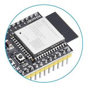
Figure 2.2: Close-up view of the ESP32-S3 module, showing the main chip and surrounding components.
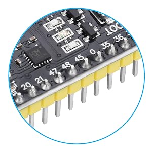
Figure 2.3: Close-up view of the ESP32-S3 development board pins, showing numbered pins, resistors, and other components.
3. Dimensions
The physical dimensions of the ESP32-S3 DevKitC-1 N16R8 module are provided below for integration into projects and enclosures.
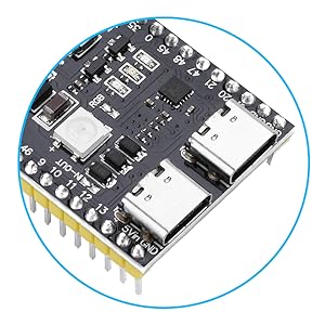
Figure 3.1: ESP32-S3 Module Dimensions. The module measures approximately 63.5mm in length and 28mm in width, with detailed measurements for pin spacing and component placement.
4. Pinout Diagram
Understanding the pinout is crucial for connecting peripherals and programming the module. The ESP32-S3 features 45 programmable GPIO pins and various communication interfaces.

Figure 4.1: ESP32-S3 Pinout Diagram. This technical diagram illustrates the pin configuration of the electronic component, with color-coded pins arranged on both sides of the central chip, indicating various functions like GPIO, ADC, DAC, UART, SPI, I2C, and power pins.
5. GPIO Extension Board
For easier access to the GPIO pins and expanded connectivity, an optional GPIO extension board can be used with the ESP32-S3 DevKitC-1 N16R8 module.

Figure 5.1: ESP32-S3 GPIO Extension Board Diagram. This image shows the layout of the extension board, indicating Digital IO Pins, 3.3V Output Pin, 5V Output Pin, DC2.1 power supply interface (6.5V-9V), ESP32-S3 Development Board Mounting Positions, and ESP32-S3 Development Board Pinout.
5.1 Extension Board Features
- Digital IO Pins: Provides clearly labeled headers for all digital input/output pins.
- 3.3V Output Pin: Dedicated 3.3V power output.
- 5V Output Pin: Dedicated 5V power output.
- DC2.1 Power Supply Interface: Accepts 6.5V-9V DC input for external power.
- Mounting Positions: Designed to securely mount the ESP32-S3 development board.
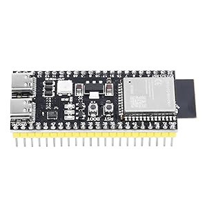
Figure 5.2: ESP32-S3 GPIO Extension Board with the development module mounted, showing multiple ports and pins for expanded connectivity.
6. Setup and Programming
To begin using your ESP32-S3 DevKitC-1 N16R8 module, you will need to set up your development environment and upload firmware.
6.1 Connecting the Module
- Connect the ESP32-S3 module to your computer using a USB Type-C cable. You can use either of the two USB-C ports on the board.
- Ensure that the necessary drivers for the USB-to-serial chip (CH343P) are installed on your computer. These drivers are typically available from the chip manufacturer's website or your operating system's default driver repository.
6.2 Firmware Upload
The ESP32-S3 supports two primary methods for uploading program files (firmware):
- Direct USB Port: Firmware can be downloaded directly via the ESP32's native USB port.
- Integrated USB-to-Serial Port: Alternatively, the integrated hardware USB-to-serial port can be used for downloading.
In a Windows environment, you can use the official Espressif flash_download_tool_xxx software for flashing firmware. For other operating systems, tools like Esptool.py are commonly used.
Before uploading, you may need to press and hold the BOOT button, then press and release the RST button, and finally release the BOOT button to put the module into download mode.
7. Operating the Module
Once programmed, the ESP32-S3 module operates according to the uploaded firmware. It supports various functionalities including Wi-Fi, Bluetooth 5.0, and GPIO control.
7.1 Wi-Fi and Bluetooth Connectivity
- The module supports Wi-Fi 802.11 b/g/n and Bluetooth 5.0 (LE).
- Its Bluetooth Low Energy subsystem supports Bluetooth 5 (LE) and Bluetooth Mesh.
- Equipped with a low-power coprocessor and a high-power mode up to 20 dBm, it can meet various application scenarios.
- Supports WMM, A-MPDU, A-MSDU, immediate block acknowledgment, and other functions to improve multitasking efficiency.
7.2 Power Consumption
The ESP32-S3 is designed for low-power performance, making it suitable for battery-powered applications. Utilize its low-power modes in your firmware to optimize energy usage.
8. Maintenance
The diymore ESP32-S3 DevKitC-1 N16R8 development module requires minimal maintenance. Keep the board clean and free from dust and moisture. Avoid exposing it to extreme temperatures or static electricity. Regularly check for updated firmware or development tools from Espressif or the diymore community for optimal performance and security.
9. Troubleshooting
- Module not recognized by computer: Ensure USB Type-C cable is functional and correctly connected. Verify that the USB-to-serial drivers (e.g., CH343P) are installed. Try a different USB port or computer.
- Firmware upload failure: Confirm the module is in download mode (press BOOT, then RST, release RST, then release BOOT). Check your development environment settings (e.g., correct COM port, baud rate). Ensure the firmware file is valid.
- Wi-Fi/Bluetooth connectivity issues: Check antenna connection (if external). Verify Wi-Fi credentials and network availability. Ensure Bluetooth device is discoverable and within range. Review your code for correct initialization and connection procedures.
- Unexpected behavior: This could be due to software bugs or hardware issues. Review your code logic. Check power supply stability. Consult online forums or the Espressif documentation for common issues related to ESP32-S3.
10. Specifications
| Feature | Description |
|---|---|
| Brand | diymore |
| Model Name | DevKitC-1 N16R8 |
| Processor | Xtensa LX7 Dual-Core 32-bit |
| CPU Manufacturer | Cadence Design Systems |
| Number of Processors | 2 |
| Memory Storage Capacity | 8 MB SRAM, 16 MB Flash |
| RAM Memory Technology | SRAM |
| Connectivity Technology | Bluetooth, GPIO, Wi-Fi |
| Wireless Communication Standard | 802.11bgn (Wi-Fi), Bluetooth 5.0 (LE) |
| Operating System | FreeRTOS |
| Compatible Devices | Personal Computer, Camera, Smartphone |
| Total USB Ports | 1 (Type-C, with pass-through and serial functionality) |
| Country of Origin | China |
11. What's in the Box
The package includes the following item:
- 1 x ESP32-S3 DevKitC-1 N16R8 Development Module
12. Warranty and Support
For warranty information and technical support, please refer to the official diymore website or contact their customer service directly. Keep your purchase receipt for any warranty claims.


