Neoteck VC746A Digital TRMS Multimeter User Manual
Model: VC746A
1. Introduction
The Neoteck VC746A is a True RMS (TRMS) digital multimeter designed for accurate and reliable electrical measurements. Featuring a 6000-count display and auto-ranging capabilities, it is suitable for both professional electricians and home users. This manual provides detailed instructions for safe operation, setup, measurement functions, maintenance, and troubleshooting.
This multimeter can measure AC/DC voltage, AC/DC current, resistance, capacitance, frequency, duty cycle, temperature, diode, and continuity. It also includes advanced safety features such as Non-Contact Voltage (NCV) detection and Live wire testing.
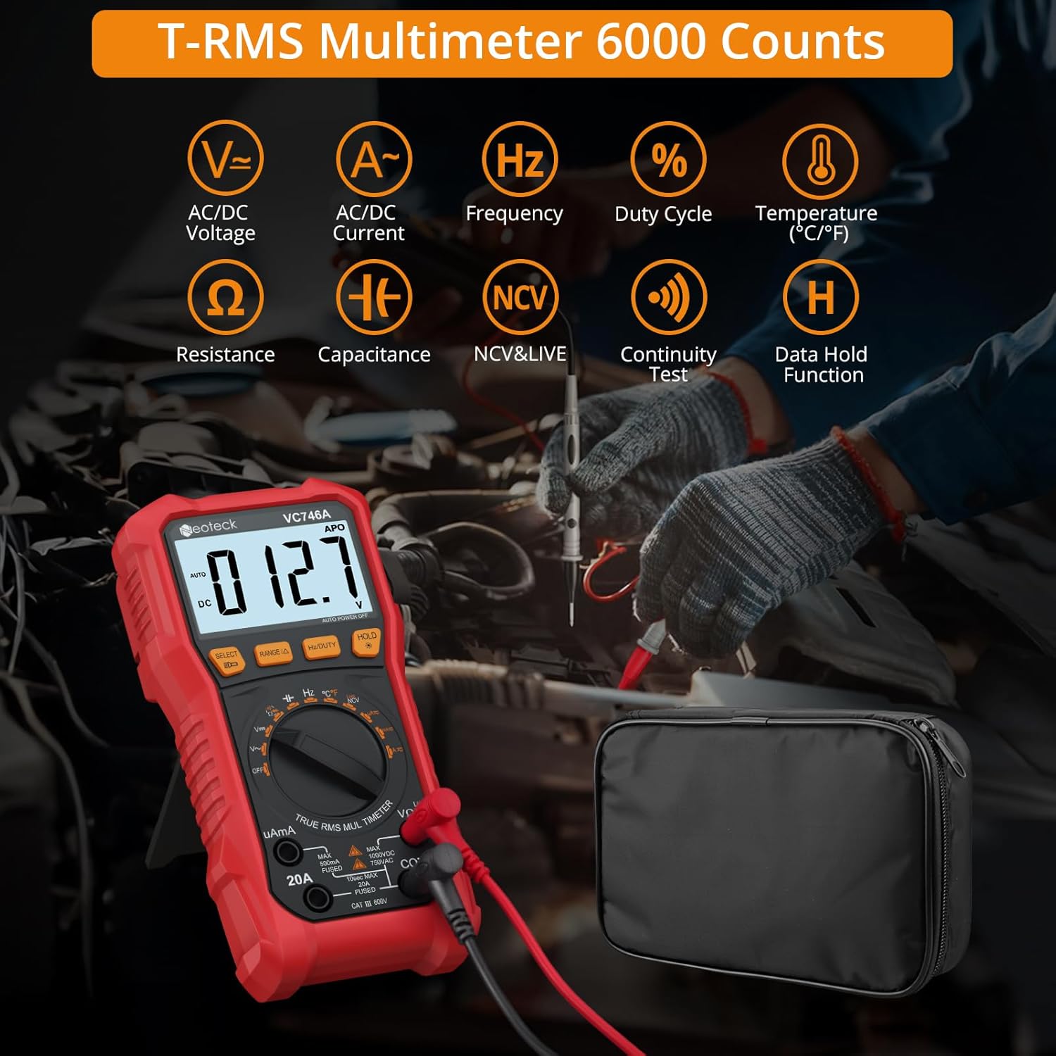
Figure 1.1: Neoteck VC746A Multimeter displaying its range of measurement capabilities including AC/DC Voltage, Current, Frequency, Duty Cycle, Temperature, Resistance, Capacitance, NCV & Live, Continuity Test, and Data Hold Function.
2. Safety Information
To ensure safe operation and avoid electric shock or personal injury, please read all safety information carefully before using the multimeter. Always adhere to local and national safety codes.
- Do not exceed the maximum input values for any function.
- Do not use the meter if it or the test leads appear damaged.
- Exercise extreme caution when working with voltages above 30V AC RMS, 42V peak, or 60V DC. These voltages pose a shock hazard.
- Always disconnect the test leads from the circuit before changing functions.
- Ensure the correct function and range are selected for the measurement.
- Use the Non-Contact Voltage (NCV) detection and Live test features to identify live wires before making contact measurements. The multimeter provides visual warnings for high voltage.
- The device features double fuse protection. If a fuse blows, replace it with one of the specified type and rating.
- Do not operate the meter in explosive gas, vapor, or dust environments.
- Keep fingers behind the finger guards on the test probes during measurements.

Figure 2.1: The multimeter's clear 3.5-inch backlit LCD display, showing a voltage warning icon to enhance safety during operation, especially in low-light conditions.

Figure 2.2: Demonstrating the Live & NCV (Non-Contact Voltage) safety detection feature, indicating the multimeter's ability to detect live wires without physical contact, providing sound and visual warnings.
3. Product Features
The Neoteck VC746A Multimeter offers a range of features for versatile and accurate electrical testing:
- True RMS (TRMS) Measurement: Provides accurate readings for non-sinusoidal waveforms.
- 6000 Counts Display: High-resolution digital display for precise measurements.
- Auto-Ranging: Automatically selects the appropriate measurement range, simplifying operation.
- Comprehensive Measurement Functions: Measures AC/DC Voltage, AC/DC Current (up to 20A), Resistance, Capacitance, Frequency, Duty Cycle, and Temperature.
- Diode and Continuity Test: Essential functions for circuit diagnostics.
- Non-Contact Voltage (NCV) Detection: Detects AC voltage without physical contact, enhancing safety.
- Live Wire Detection: Identifies live wires for safe electrical work.
- Large Backlit LCD Screen: Ensures clear readability even in dimly lit environments.
- Integrated Flashlight: Provides illumination for working in dark areas.
- Data Hold Function: Freezes the displayed reading for convenient recording.
- Kickstand and Pen Holder Design: Allows for hands-free operation and convenient storage of test leads.
- Protective Rubber Case: Durable casing for enhanced protection against drops and impacts.
- Automatic Power Off: Conserves battery life when not in use.
- Low Battery Indicator: Alerts when batteries need replacement.

Figure 3.1: An overview of the Neoteck VC746A Multimeter's comprehensive capabilities, including Voltage, Current, Temperature, Diode, Duty Cycle, Frequency, Capacitance, Resistance, Continuity, TRMS 6000 Counts, Data Hold, and Flashlight.
4. Package Contents
Verify that all items are present in your package:
- Neoteck VC746A Digital TRMS Multimeter
- Test Leads (1 pair)
- Temperature Probe
- Alligator Clips (1 pair)
- Screwdriver
- AA Batteries (2 pcs)
- Storage Bag
- User Manual (this document)

Figure 4.1: The complete package contents, including the Neoteck VC746A Multimeter, test leads, temperature probe, alligator clips, screwdriver, AA batteries, storage bag, and operation manual.

Figure 4.2: Close-up view of the included accessories (test leads, alligator clips, temperature probe), the integrated pen holder design, the protective rubber case, and the foldable stand support for hands-free convenience.
5. Setup
5.1 Battery Installation
- Ensure the multimeter is turned off.
- Locate the battery compartment cover on the back of the multimeter.
- Use the included screwdriver to loosen the screw securing the battery cover.
- Remove the cover and insert two AA batteries, observing the correct polarity (+/-).
- Replace the battery cover and tighten the screw.
5.2 Connecting Test Leads
- Insert the black test lead into the "COM" (Common) input jack.
- For most voltage, resistance, continuity, diode, capacitance, and frequency measurements, insert the red test lead into the "VΩHz" input jack.
- For current measurements (up to 600mA), insert the red test lead into the "uAmA" input jack.
- For high current measurements (up to 20A), insert the red test lead into the "20A" input jack.
6. Operating Instructions
6.1 General Operation
- Power On/Off: Rotate the rotary switch to the desired function to turn on the multimeter. Rotate to "OFF" to turn it off.
- Auto Range: The multimeter automatically selects the best measurement range. Press the "RANGE" button to switch to manual ranging if desired. Press again to return to auto-ranging.
- Data Hold: Press the "HOLD" button to freeze the current reading on the display. Press again to release.
- Backlight/Flashlight: Press and hold the "HOLD" button to turn on the backlight. Press it again to turn on the flashlight. A third press turns off both.
- Function Selection: For functions with multiple modes (e.g., AC/DC Voltage, Diode/Continuity), press the "SELECT" button to cycle through the modes.
6.2 Measurement Functions
Always ensure the test leads are connected to the correct input jacks and the rotary switch is set to the appropriate function before making any measurements.
6.2.1 AC/DC Voltage Measurement (V∼ / V—)
- Set the rotary switch to "V".
- Press "SELECT" to choose between AC (V∼) or DC (V—) voltage.
- Connect the test leads in parallel to the circuit or component under test.
- Read the voltage value on the display.
6.2.2 AC/DC Current Measurement (uA∼/—, mA∼/—, A∼/—)
- Set the rotary switch to "uAmA" or "20A" depending on the expected current.
- Press "SELECT" to choose between AC (∼) or DC (—) current.
- Important: Disconnect power to the circuit. Open the circuit where the current is to be measured. Connect the multimeter in series with the circuit.
- Apply power to the circuit. Read the current value on the display.
- After measurement, disconnect power, remove the multimeter, and restore the circuit.
6.2.3 Resistance Measurement (Ω)
- Set the rotary switch to "Ω".
- Ensure the circuit is de-energized and any capacitors are discharged.
- Connect the test leads across the component to be measured.
- Read the resistance value on the display.
6.2.4 Capacitance Measurement (㎏)
- Set the rotary switch to "㎏".
- Ensure the capacitor is fully discharged before connecting the test leads.
- Connect the test leads across the capacitor.
- Read the capacitance value on the display.
6.2.5 Frequency (Hz) and Duty Cycle (%) Measurement
- Set the rotary switch to "Hz%".
- Press "SELECT" to toggle between Frequency (Hz) and Duty Cycle (%).
- Connect the test leads in parallel to the signal source.
- Read the frequency or duty cycle value on the display.
6.2.6 Temperature Measurement (℃/℉)
- Set the rotary switch to "TEMP".
- Connect the temperature probe to the input jacks (red to VΩHz, black to COM).
- Place the tip of the temperature probe on the object or in the environment to be measured.
- Read the temperature value on the display. Press "SELECT" to switch between Celsius (℃) and Fahrenheit (℉).
6.2.7 Diode Test (→|—)
- Set the rotary switch to "→|—" (Diode/Continuity).
- Press "SELECT" to select the Diode Test function.
- Connect the red test lead to the anode and the black test lead to the cathode of the diode.
- A forward voltage drop will be displayed. Reverse the leads; an open circuit (OL) should be displayed for a good diode.
6.2.8 Continuity Test (♪)
- Set the rotary switch to "→|—" (Diode/Continuity).
- Press "SELECT" to select the Continuity Test function.
- Connect the test leads across the circuit or component.
- If the resistance is below approximately 50Ω, the buzzer will sound, indicating continuity.
6.2.9 Non-Contact Voltage (NCV) Detection
- Set the rotary switch to "NCV/LIVE".
- Press "SELECT" to select the NCV function.
- Move the top end of the multimeter near the conductor or outlet.
- The meter will beep and the NCV indicator light will flash with increasing frequency as it detects AC voltage.
6.2.10 Live Wire Detection
- Set the rotary switch to "NCV/LIVE".
- Press "SELECT" to select the LIVE function.
- Insert the red test lead into the live wire or socket hole. The black lead is not used for this test.
- The display will show "LIVE" and the meter will beep and flash if a live wire is detected.
7. Maintenance
7.1 Cleaning
Wipe the case with a damp cloth and mild detergent. Do not use abrasives or solvents. Keep the input terminals free of dirt and moisture.
7.2 Battery Replacement
When the low battery indicator appears on the display, replace the batteries as described in Section 5.1. Always use two new AA batteries.
7.3 Fuse Replacement
If the current measurement function fails, the fuse may need replacement. Refer to the specifications for the correct fuse type and rating. Fuse replacement should only be performed by qualified personnel.
7.4 Storage
If the multimeter is not used for an extended period, remove the batteries to prevent leakage. Store the device in a cool, dry place, away from direct sunlight and extreme temperatures.
8. Troubleshooting
| Problem | Possible Cause | Solution |
|---|---|---|
| Meter does not power on. | Dead batteries; Incorrect battery installation. | Replace batteries; Check battery polarity. |
| "OL" (Overload) displayed. | Input value exceeds selected range; Open circuit (for continuity/resistance). | Switch to a higher range (if in manual range); Check circuit connection. |
| Inaccurate readings. | Incorrect function selected; Poor test lead connection; External interference. | Verify function and range; Ensure secure connections; Move away from strong electromagnetic fields. |
| Current measurement not working. | Blown fuse; Incorrect input jack. | Replace fuse (see Section 7.3); Ensure red lead is in "uAmA" or "20A" jack. |
| NCV/LIVE not detecting. | Weak signal; Shielded wires. | Ensure close proximity to conductor; NCV may not detect through thick insulation or metal conduits. |
9. Specifications
| Parameter | Value |
|---|---|
| Model Number | VC746A |
| Display | 6000 Counts, Backlit LCD |
| True RMS | Yes |
| Auto Range | Yes |
| DC Voltage | Up to 1000V |
| AC Voltage | Up to 750V |
| DC Current | Up to 20A |
| AC Current | Up to 20A |
| Resistance | Yes |
| Capacitance | Yes |
| Frequency | Yes |
| Duty Cycle | Yes |
| Temperature | Yes (with included probe) |
| Diode Test | Yes |
| Continuity Test | Yes (with buzzer) |
| NCV Detection | Yes |
| Live Wire Detection | Yes |
| Power Source | 2 x AA Batteries |
| Dimensions (L x W x H) | 19 x 9.2 x 4.5 cm |
| Weight | 480 Grams |
10. Warranty and Support
Neoteck products are designed for reliability and performance. For warranty information or technical support, please refer to the contact details provided with your purchase or visit the official Neoteck website. Keep your purchase receipt as proof of purchase for warranty claims.


