1. Introduction
This manual provides essential information for the safe and efficient installation, operation, and maintenance of your CTDOFUM ATV71 Series Variable Frequency Drive (VFD), model ATV71HU30N4Z. The ATV71 Series VFD is designed to control the speed of AC motors, offering precise control and energy efficiency for various industrial applications. Please read this manual thoroughly before attempting any procedures to ensure proper understanding and to prevent potential hazards or equipment damage.
2. Safety Information
WARNING: High voltage. Risk of electric shock. Only qualified and authorized personnel should install, operate, and maintain this equipment. Failure to follow these instructions can result in serious injury or death.
- Always disconnect all power sources to the VFD and wait for the DC bus capacitors to discharge completely before performing any work on the unit. Verify zero voltage with a multimeter.
- Ensure proper grounding of the VFD and the motor in accordance with local and national electrical codes.
- Protect the VFD from moisture, dust, corrosive gases, and direct sunlight.
- Do not operate the VFD with covers removed.
- Use appropriate personal protective equipment (PPE) when working with electrical equipment.
- Never connect the main power supply to the motor output terminals (U, V, W).
3. Product Overview
The CTDOFUM ATV71 Series VFD is a robust and efficient solution for controlling the speed and torque of three-phase AC induction motors. It is designed for demanding industrial applications requiring high performance and reliability.
Key Features:
- Precise speed and torque control.
- Energy saving capabilities through optimized motor control.
- Integrated protection functions for motor and VFD.
- User-friendly interface for configuration and monitoring.
- Suitable for 480V AC power systems.
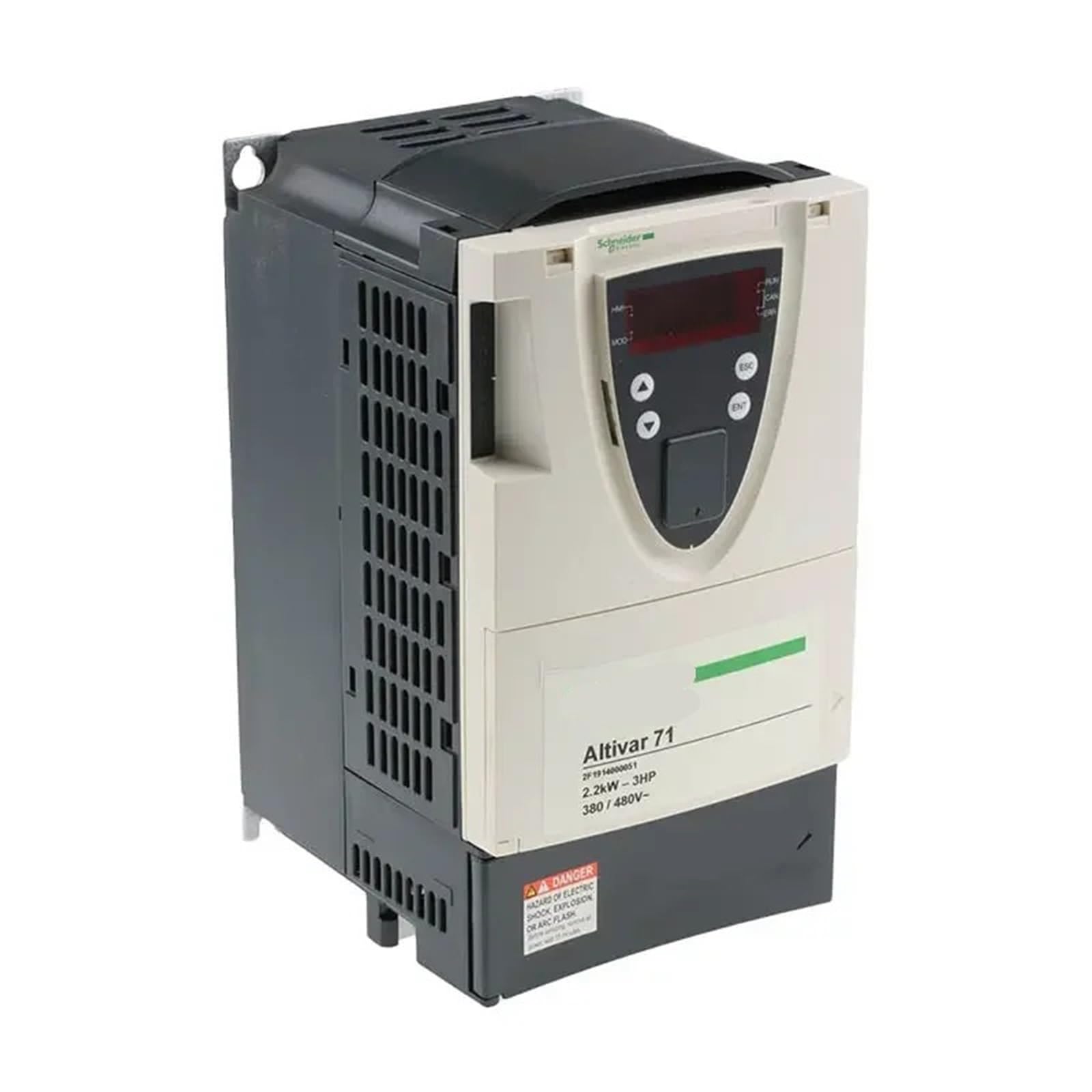
Figure 1: Front view of the CTDOFUM ATV71 Series Variable Frequency Drive. This image shows the main casing and the control panel interface.
4. Setup and Installation
4.1. Unpacking and Inspection
Carefully unpack the VFD from its packaging. Inspect the unit for any signs of physical damage that may have occurred during shipping. If any damage is found, contact your supplier immediately and do not attempt to install or power on the unit.
4.2. Mounting
Mount the VFD vertically on a flat, non-flammable surface within a suitable electrical enclosure. Ensure adequate clearance (minimum 10 cm above and below, 5 cm on sides) for proper airflow and heat dissipation. Avoid mounting in direct sunlight or near heat sources.
4.3. Wiring
All wiring must be performed by a qualified electrician in accordance with all applicable electrical codes.
- Power Input (L1, L2, L3): Connect the 480V AC three-phase power supply to the input terminals.
- Motor Output (U, V, W): Connect the three-phase motor leads to the output terminals. Ensure correct phase sequence.
- Grounding (PE): Connect the protective earth (ground) terminal of the VFD to the main grounding system.
- Control Wiring: Connect control signals (e.g., start/stop, speed reference, fault relays) to the designated control terminals. Refer to the detailed wiring diagrams in the full product manual for specific terminal assignments.
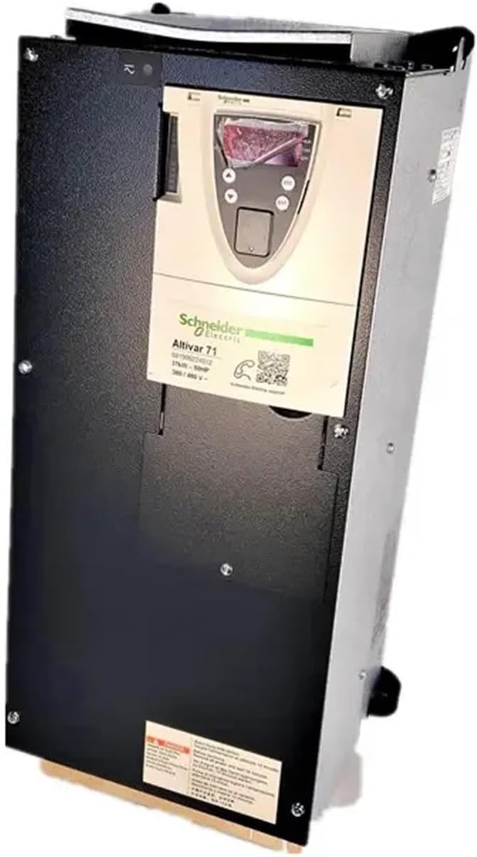
Figure 2: Side view of the CTDOFUM ATV71 Series VFD, illustrating potential mounting points and general layout for electrical connections.
4.4. Initial Power-Up
Before connecting the motor, apply power to the VFD. Observe the display for any error codes or abnormal indications. If the display shows a normal standby state, proceed to parameter configuration.
5. Operating Instructions
5.1. Control Panel
The VFD features a local control panel with a display and navigation buttons for monitoring and parameter adjustment.
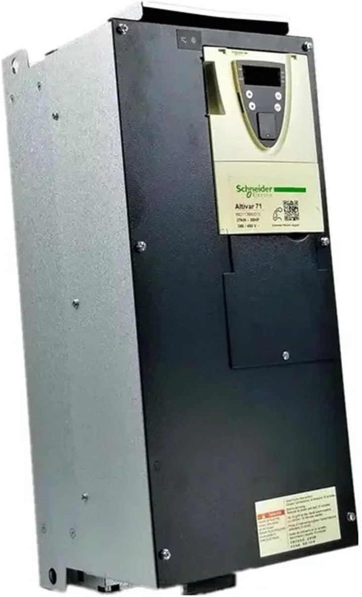
Figure 3: Close-up view of the CTDOFUM ATV71 Series VFD, showing the control panel with display and buttons for user interaction.
5.2. Parameter Configuration
Before operating the motor, configure the essential motor parameters. These typically include:
- Motor Nominal Voltage (e.g., 480V)
- Motor Nominal Current
- Motor Nominal Frequency (e.g., 60 Hz)
- Motor Nominal Speed (RPM)
- Acceleration and Deceleration Times
- Control Mode (e.g., V/F control, Sensorless Vector Control)
Refer to the detailed programming guide for a complete list of parameters and their functions.
5.3. Start/Stop Operation
- Local Control: Press the START button on the control panel to begin motor operation. Press the STOP button to halt the motor.
- Remote Control: If configured for remote control, activate the designated digital input for start/stop commands.
5.4. Speed Adjustment
Motor speed can be adjusted via the control panel potentiometer, digital inputs, or analog input signals, depending on the VFD's configuration.
6. Maintenance
Regular maintenance ensures the longevity and reliable operation of your VFD. Always disconnect power and wait for discharge before performing any maintenance.
- Cleaning: Periodically clean the VFD's exterior and cooling fins to prevent dust accumulation. Use a soft, dry cloth. For internal cleaning, use dry, oil-free compressed air.
- Cooling Fan Inspection: Check the cooling fans for proper operation, unusual noises, or obstructions. Replace fans if they are faulty or excessively noisy.
- Terminal Tightness: Annually inspect all power and control terminal connections for tightness. Loose connections can cause overheating and damage.
- Environmental Check: Ensure the operating environment remains within specified temperature and humidity limits.
7. Troubleshooting
This section provides solutions for common issues. For complex problems or persistent faults, contact technical support.
| Problem | Possible Cause | Solution |
|---|---|---|
| Motor does not start. | No power supply, incorrect wiring, fault condition, parameter error. | Check power input, verify wiring, clear fault codes, review motor parameters. |
| Overcurrent fault (OCF). | Motor overload, short circuit in motor or wiring, incorrect acceleration time, VFD undersized. | Reduce motor load, check motor and cables for shorts, increase acceleration time, ensure VFD matches motor rating. |
| Overvoltage fault (OVF). | High input voltage, regeneration from motor (e.g., rapid deceleration), incorrect deceleration time. | Check input voltage, increase deceleration time, consider adding a braking resistor if regeneration is significant. |
| Motor runs erratically or vibrates. | Incorrect motor parameters, loose motor connections, motor damage. | Verify motor parameters, check motor wiring, inspect motor for damage. |
8. Specifications
| Brand | CTDOFUM |
| Model Number | ATV71HU30N4Z |
| Power Rating | 3.0 KW (4.0 HP) |
| Input Voltage | 480V AC |
| ASIN | B0FVM2B64M |
| Item Weight | 1.76 ounces (Note: This value may refer to a component, not the entire unit.) |
| Package Dimensions | 0.39 x 0.39 x 0.39 inches (Note: This value appears to be a placeholder or incorrect.) |
| Manufacturer | CTDOFUM |
9. Warranty and Support
For detailed warranty information, technical assistance, or to report any issues with your CTDOFUM ATV71 Series VFD, please contact your authorized CTDOFUM distributor or visit the official CTDOFUM website. Please have your model number (ATV71HU30N4Z) and purchase details ready when contacting support.