Introduction
This manual provides detailed instructions for the eletechsup 30A DC 12V/24V Relay Module, a versatile controller designed for brushed DC motors. It enables forward and reverse operation with various control modes, suitable for applications such as automatic doors, curtains, and other pusher motor systems. Please read this manual thoroughly before installation and operation to ensure correct usage and optimal performance.
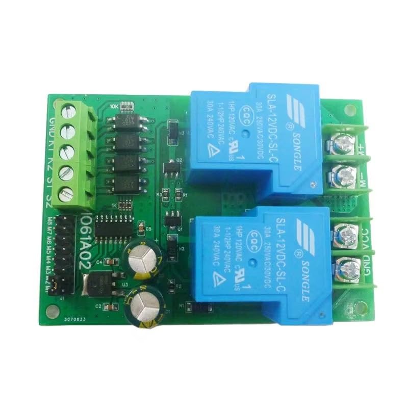
Image: Overview of the eletechsup 30A DC 12V Relay Module. This image displays the compact design of the module, highlighting its two blue relays and green terminal blocks for connections.
Setup and Connections
Power Requirements
- Working Voltage: DC 12V (for 12V version) or DC 24V (for 24V version).
- Power Supply: The DC power supply capacity must be at least 3 times the motor load (Power Supply ≥ Motor Load x 3).
- Voltage Range: DC 11-15V for the 12V version; DC 22-26V for the 24V version.
- Connection: Connect the power supply to the 'VIN' (positive) and 'GND' (negative) terminals. Ensure correct polarity.
- Compatible Power Sources: Switching power supplies, DC output transformers, lead-acid batteries, lithium batteries, solar batteries, etc.
Motor Requirements
- Applicable Motor: Brushed DC motor only.
- Connection: Connect motor wires to 'Motor+' and 'Motor-' terminals.
- Power Limits:
- For 24V DC motors: Rated power less than 100W (limit 200W).
- For 12V DC motors: Rated power less than 50W (limit 100W).
Module Pinout and Mode Selection
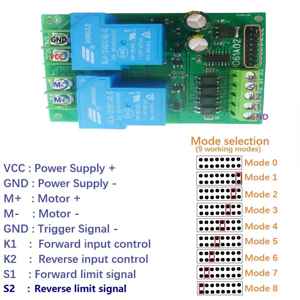
Image: Pinout diagram and mode selection jumpers. This image illustrates the various connection terminals (VCC, GND, M+, M-, K1, K2, S1, S2) and the jumper settings for selecting one of the 9 working modes.
The module features several terminals for power, motor, and signal input, along with jumpers for mode selection:
- VCC: Power Supply Positive (+)
- GND: Power Supply Negative (-) / Trigger Signal Negative (-)
- M+: Motor Positive (+)
- M-: Motor Negative (-)
- K1: Forward Input Control Signal
- K2: Reverse Input Control Signal
- S1: Forward Limit Signal Input
- S2: Reverse Limit Signal Input
Working modes (0-8) are selected using the onboard jumpers. Refer to the diagram for specific jumper configurations for each mode.

Image: Basic power supply and motor connection. This diagram shows how to connect a DC power supply and a brushed DC motor to the module, emphasizing the VCC, GND, M+, and M- terminals.
Operating Instructions
Signal Input Terminals
The module has four signal input terminals: 'K1', 'K2', 'S1', and 'S2'.
- K1: Forward rotation signal input.
- K2: Reverse rotation signal input.
- S1: Forward limit signal input.
- S2: Reverse limit signal input.
Signal inputs are active low (NPN). A short-term 0V level (negative power supply) will trigger the signal. The signal source can be a micro switch, induction sensor, infrared sensor, metal sensor, remote control module, or a single-chip microcomputer.
Working Modes (9 Optional Modes)
The module offers 9 distinct working modes, selected via jumpers. The general behavior for most modes includes:
- When a reverse signal is encountered during forward rotation, the motor stops for 0.3 seconds before reversing.
- Limit signals have priority. A forward limit signal immediately stops forward rotation.
- Forward rotation cannot start if a forward limit signal is active, and similarly for reverse rotation.
- Limit signals are normally open. For example, if the SW1 switch is closed or connected to a low level, forward rotation cannot be started.
- Only one limit signal is valid at a time. Inputting two limit signals simultaneously during reverse rotation will not stop the motor.
Mode 0: Standard Self-Locking (Base Mode)
This is the foundational mode. A signal trigger initiates and self-locks the motor's operation until a stop condition (e.g., limit switch or opposing signal) is met.
Mode 1: Automatic Start Version
Adds an automatic power-on start function to Mode 0. Each time the module is powered on, it automatically starts forward rotation. This mode is suitable for applications where the module needs to automatically move between two points upon power-up.
Mode 2: Momentary Mode
The motor rotates forward as long as a forward rotation signal is present. It reverses as long as a reverse rotation signal is present. The motor stops when no forward or reverse signal is active. If a forward limit is reached during forward rotation, it stops. If a reverse limit is reached during reverse rotation, it stops. Removing limit signals does not restore rotation; a new rotation signal is required to restart.
Mode 3: Level-Driven Mode
Functions similarly to an H-bridge. It rotates forward when a forward signal is present and no forward limit is active. It reverses when a reverse signal is present and no reverse limit is active. This is a pure logic-type mode, suitable for single-chip signal input. Forward rotation has priority: if both forward and reverse input conditions are met, it will rotate forward. The motor's rotation is real-time based on the level of the signals. Limit input is invalid when the motor is rotating, meaning the motor cannot be stopped by limit signals in this mode.
Mode 4: Start/Stop Mode
Similar to Mode 0, but with a modified stop function. If forward rotation is active, inputting the forward rotation signal again will immediately stop it. The same applies to reverse rotation. For example, a forward signal starts forward rotation; inputting the forward signal again stops it.
Mode 5: Limit Signal Current Validity
Similar to Mode 0, but the limit signal is only valid for the current instance (leading edge valid). After starting forward rotation, it stops when the forward limit signal is encountered. Even if the forward limit signal remains active after stopping, forward rotation can be restarted by inputting the forward rotation signal again. This mode is useful when unidirectional start and end points are on the same motion path, e.g., pressing once to complete one cycle.
Mode 6: One-Key Switch Mode
Similar to Mode 0, but with a different starting method. The forward rotation signal input triggers forward rotation. Re-triggering the same signal initiates reverse rotation. The reverse rotation signal input is invalid in this mode. Inputting the forward rotation signal once starts forward rotation, stopping at the forward limit. Inputting it again starts reverse rotation, stopping at the reverse limit.
Mode 7: Forward/Reverse Signal Priority
Rotates forward when a forward rotation signal is input. Reverses when no signal is present. The reverse rotation signal input is invalid and cannot be used with other signals. During forward rotation, the forward limit signal stops it. During reverse rotation, the reverse limit signal stops it. Only one limit signal is valid at a time. For example, inputting two limit signals simultaneously during reverse rotation will not stop the motor.
Mode 8: Self-Locking - Limit Normally Closed Mode
Similar to Mode 0, but the limit signal is normally closed. For example, if there is no signal input to the forward limit, forward rotation cannot be started. Forward rotation can only be initiated when the forward limit signal is actively input (i.e., the normally closed circuit is opened).
Wiring Diagrams for Common Applications (Mode 0 Examples)
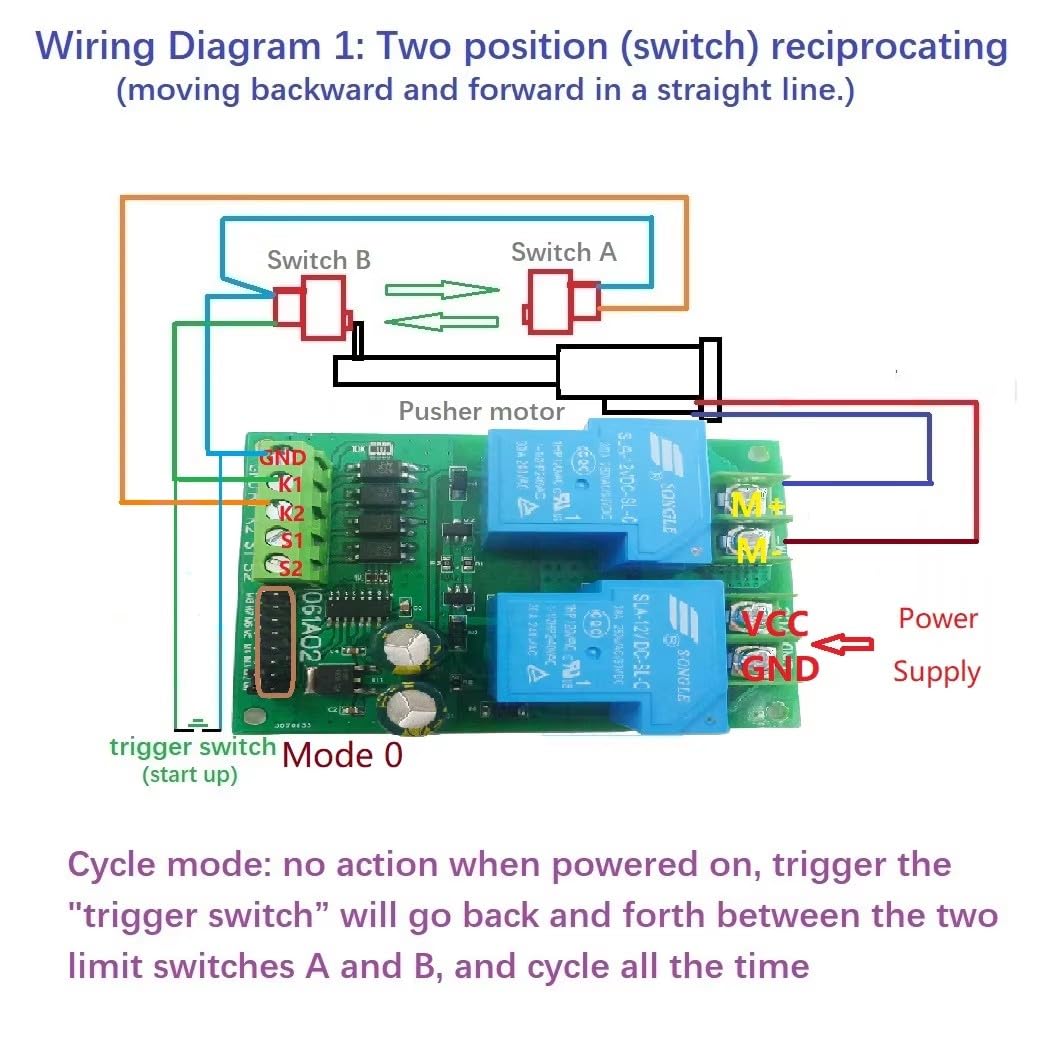
Image: Wiring Diagram 1 for two-position reciprocating motion (Mode 0). This diagram shows connections for a pusher motor with two limit switches (Switch A and Switch B) and a trigger switch for continuous back-and-forth movement.
Wiring Diagram 1: Two-Position Reciprocating (Moving Backward and Forward in a Straight Line)
- No action upon power-on.
- Triggering the "trigger switch" (connected to K1) will cause the motor to move back and forth continuously between limit switches A and B.
- This cycle will repeat indefinitely until power is removed or another stop condition is met.

Image: Wiring Diagram 2 for independent forward/reverse start/stop (Mode 0). This diagram illustrates how to connect two separate trigger buttons (B1 and B2) to control forward and reverse motion, stopping at respective limit switches.
Wiring Diagram 2: Positive and Negative Start Independently, Each Time Running a Single Pass
- Trigger B1 (connected to K1) to start forward rotation. The pusher motor extends until it touches Switch B (connected to S2), then stops.
- Trigger B2 (connected to K2) to start reverse rotation. The pusher motor retracts until it hits Switch A (connected to S1), then stops.

Image: Wiring Diagram 3 for a forward and reverse cycle (Mode 0). This diagram shows a single trigger button (B1) initiating a sequence of forward motion to Switch B, then reverse motion to Switch A, completing one cycle.
Wiring Diagram 3: Every Time You Start, Run a Forward and Reverse Rotation
- Trigger B1 (connected to K1) to start forward rotation.
- When the motor hits Switch B (connected to S2), it reverses direction.
- The motor continues in reverse until it hits Switch A (connected to S1), at which point it stops, ending the action.
Maintenance
The eletechsup Relay Module is designed for reliable operation with minimal maintenance. To ensure longevity and proper function:
- Keep the module clean and free from dust, moisture, and corrosive substances.
- Periodically inspect all wiring connections to ensure they are secure and free from damage.
- Avoid exposing the module to extreme temperatures or direct sunlight.
Troubleshooting
If the module is not functioning as expected, consider the following:
- No Motor Movement:
- Check power supply voltage and polarity.
- Ensure motor connections are correct and secure.
- Verify the motor is a brushed DC type and within specified power limits.
- Confirm the selected working mode and corresponding signal inputs.
- Incorrect Motor Behavior:
- Review the specific working mode description to ensure it matches desired operation.
- Check signal input connections (K1, K2, S1, S2) and their active low status.
- Inspect limit switches for proper function and wiring.
- Intermittent Operation:
- Check for loose connections or damaged wiring.
- Ensure the power supply is stable and provides sufficient current (≥ motor load x 3).
Technical Specifications
| Parameter | Value |
|---|---|
| Working Voltage | DC 12V (12V version) or DC 24V (24V version) |
| Applicable Motor | Brushed DC motor |
| Maximum Load Current | 15A (Relay maximum load 30A) |
| Signal Input | Active low (NPN) |
| Working Modes | 9 optional modes (Momentary, Self-locking, etc.) |
| Working Current (excluding motor) | Quiescent: 5mA, Forward/Reverse: 70mA |
| Module Size | 89mm * 62mm * 22mm |
| Module Weight | 85 grams |
| 12V DC Motor Power Limit | Rated < 50W, Limit 100W |
| 24V DC Motor Power Limit | Rated < 100W, Limit 200W |
Warranty Information
This eletechsup product is covered by the manufacturer's standard warranty. Please refer to the product packaging or contact the seller for specific warranty terms and conditions. Keep your proof of purchase for any warranty claims.
Customer Support
For technical assistance, troubleshooting, or any questions regarding the eletechsup 30A DC 12V/24V Relay Module, please contact eletechsup customer support through the platform where the product was purchased. Provide your product model (IO56D02) and a detailed description of the issue for efficient support.