1. Introduction
The ULNA AX3000 WiFi6 Wireless Bridge Outdoor CPE806S is designed for extending network connectivity over long distances in outdoor environments. Utilizing the latest WiFi 6 technology, this dual-band wireless bridge offers improved efficiency, capacity, and reduced latency for seamless point-to-point (PTP) and point-to-multipoint (PTMP) connections. It is ideal for expanding networks to outbuildings, ranches, shops, or for enhancing outdoor surveillance systems.
2. Key Features
- Next-Gen WiFi 6 Technology: Enhanced efficiency, capacity, and reduced latency for long-range connections.
- 5KM Stable Wireless Transmission: Equipped with 5x 16dBi directional antennas for reliable point-to-point connectivity up to 5 kilometers.
- 2.5Gbps & 1Gbps Dual Ethernet Ports: Supports high-speed data transfer for 4K streaming, IP camera video feeds, and fast file sharing.
- Dual Band WiFi Access: Provides 2.4GHz and 5.8GHz WiFi access at both ends, allowing direct connection for multiple devices without an additional router.
- Two Power Options: Supports 24V passive POE and 12V/1A DC solar panel input for flexible outdoor power solutions.
- Hassle-Free Plug & Play Setup: Pre-configured for instant pairing upon power-up, requiring no technical expertise.
- PTP & PTMP Modes: Versatile transmission modes for various network expansion and surveillance applications.
- IP65-Rated Outdoor Design: Durable, waterproof housing suitable for harsh outdoor environments.
3. What's in the Box

Image: All components included in the ULNA CPE806S Wireless Bridge kit.
- 2 × CPE806S Wireless Bridge Units
- 2 × 24V 1000Mbps PoE Adapters
- 2 × 3FT Test Ethernet Cables
- 2 × Bracket Mounts
- Metal Straps (for mounting)
- Full Hardware Kit (screws, anchors)
- 1 × User Manual
4. Product Overview
4.1 Unit Components

Image: Front view of the ULNA CPE806S Wireless Bridge unit.
Each CPE806S unit features a sleek, weather-resistant design suitable for outdoor installation. The front panel includes the ULNA logo and integrated antennas for optimal signal transmission.
4.2 Ports and Indicators

Image: Rear view of the CPE806S unit, showing the port cover removed to reveal Ethernet ports, power input, and LED indicators.
- 2.5Gbps LAN Port: High-speed Ethernet port for primary data connection.
- 1Gbps LAN Port: Standard Ethernet port for secondary data connection or local device access.
- Power Input: 24V passive POE or 12V/1A DC input.
- Reset Button: Used to restore factory settings.
- Digital Display: Shows the current channel number for pairing.
- LED Indicators: Display power status, LAN activity, and wireless signal strength.
5. Setup Guide
5.1 Initial Pairing (Plug & Play)

Image: Step-by-step diagram illustrating the simple plug-and-play setup process.
The CPE806S units are pre-configured for instant pairing. Simply power on both units, and they will automatically establish a connection. No complex configuration is required for basic point-to-point operation.
- Connect the included 24V PoE adapter to the PoE port of the first CPE806S unit (Master Bridge).
- Connect the included 24V PoE adapter to the PoE port of the second CPE806S unit (Slave Bridge).
- Power on both PoE adapters. The units will automatically pair.
- Verify successful pairing by checking the LED indicators on both units.
5.2 Connecting to Your Network
Video: Official setup guide for the ULNA CPE806S AX3000 WiFi 6 Wireless Bridge, demonstrating physical connections and initial pairing.
- Connect the Master Bridge's LAN port (2.5Gbps or 1Gbps) to your main router or network switch using an Ethernet cable.
- At the remote location, connect the Slave Bridge's LAN port (2.5Gbps or 1Gbps) to your desired device (e.g., PC, IP camera, secondary router) using an Ethernet cable.
- The Slave Bridge also provides dual-band WiFi access, allowing wireless devices to connect directly at the remote location.
6. Mounting Instructions
6.1 Mounting Options
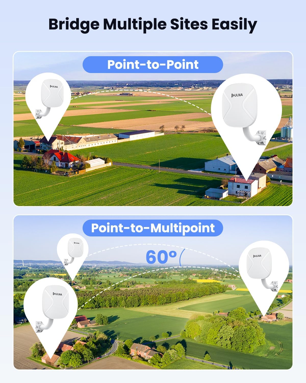
Image: The CPE806S unit mounted on an outdoor pole, demonstrating its adjustable bracket and weather-resistant design.
The CPE806S units come with mounting brackets and metal straps for flexible installation. They can be mounted on poles or directly to a wall.
- Attach the mounting bracket to the desired location (pole or wall) using the provided screws and metal straps.
- Secure the CPE806S unit to the mounting bracket. Ensure the unit is firmly attached and can be adjusted for optimal alignment.
- Adjust the angle of the unit to ensure a clear line of sight between the Master and Slave Bridges for best performance.
7. Application Cases
7.1 Point-to-Point (PTP) & Point-to-Multipoint (PTMP)

Image: Visual representation of how the CPE806S can be configured for both Point-to-Point and Point-to-Multipoint network extensions.
The CPE806S supports both PTP and PTMP modes. In PTP mode, two units establish a direct link. In PTMP mode, one Master Bridge can connect to multiple Slave Bridges (within a 60-degree angle) to extend the network to several locations.
7.2 Network Extension Scenarios

Image: Diagram illustrating how ULNA wireless bridges can extend a network from a main building to a remote building, sharing internet access.
- Building-to-Building WiFi: Extend your home or office network to a detached garage, barn, or guesthouse.
- Starlink Coverage Extension: Distribute high-speed Starlink internet to remote sheds or tiny homes.
- Long-Distance IP Camera Deployment: Connect IP cameras over long distances for surveillance systems without running extensive cables.
8. Access to Web Interface

Image: Diagram showing a computer connected to the CPE806S via a PoE adapter and Ethernet cable to access the web interface.
While the CPE806S is plug-and-play for basic operation, advanced settings can be configured via a web interface. To access it:
- Connect your computer directly to the LAN port of either the Master or Slave Bridge using an Ethernet cable.
- Ensure your computer's IP address is on the same network segment as the bridge (refer to the user manual for default IP addresses).
- Open a web browser and enter the bridge's default IP address (e.g., 192.168.255.100 for Master, 192.168.255.200 for Slave).
- Log in using the default username and password (refer to the user manual).
- From the web interface, you can customize WiFi name, password, channel, IP settings, and other advanced features.
9. Specifications
| Brand | ULNA |
| Model Name | CPE806S |
| Wireless Communication Standard | 802.11ac, 802.11ax (WiFi 6), 802.11b, 802.11g, 802.11n |
| Frequency Band Class | Dual-Band (2.4GHz & 5.8GHz) |
| Connectivity Technology | Ethernet, Wi-Fi |
| Special Features | Access Point Mode, Guest Mode, Internet Security, LED Indicator, Weatherproof (IP65-rated) |
| Ethernet Ports | 1x 2.5Gbps LAN, 1x 1Gbps LAN |
| Power Options | 24V Passive POE, 12V/1A DC Solar Panel Input (Not compatible with 48V POE) |
| Wireless Transmission Range | Up to 5KM (Point-to-Point) |
| Antennas | 5x 16dBi Directional Antennas |
| Item Weight | 7.58 pounds |
| Package Dimensions | 17.5 x 9.7 x 9.5 inches |
10. Troubleshooting
- No Power: Ensure the PoE adapter is correctly connected and plugged into a working power outlet. Verify the power LED indicator is on.
- No Connection Between Bridges: Ensure both Master and Slave Bridges are powered on and have a clear line of sight. Check that the digital display on both units shows the same channel number. If not, use the reset button to cycle channels until they match.
- Poor Signal Strength: Adjust the alignment of both bridges to optimize signal strength. Ensure there are no obstructions between the units. Check the signal strength LEDs for optimal positioning.
- No Internet Access: Verify that the Master Bridge is correctly connected to your main router/modem and that your main internet connection is active. Check all Ethernet cable connections.
- Cannot Access Web Interface: Ensure your computer's IP address is compatible with the bridge's default IP range. Try temporarily setting your computer's IP to a static address within the bridge's subnet.
11. Warranty & Support
For warranty information and technical support, please refer to the official ULNA website or contact ULNA customer service directly. The user manual included in the package also contains detailed support contact information.


