1. Introduction
This manual provides essential information for the safe and efficient installation, operation, and maintenance of your Garvee 20K BTU Dual Zone Mini Split AC/Heating System. Please read it thoroughly before installation and keep it for future reference.
Your Garvee Mini Split system offers high-efficiency heating and cooling with independent climate control for two zones. Key features include:
- 20 SEER2 High Efficiency: Fully inverter-driven system compatible with 208-230V households, designed for energy savings.
- Dual-Zone Independent Control: Two 9,000 BTU indoor units allow personalized comfort settings for each room via remote, Wi-Fi, or voice control.
- Multiple Operating Modes: Adjust settings with Turbo, ECO, Sleep, Silent, Timer, I FEEL, I SET, and 8°C heating modes.
- Whisper Quiet Operation: The AC split unit operates as low as 42dB for minimal disturbance.
2. Safety Information
Professional Installation Required: The air conditioner must be installed by professional personnel to ensure safety, optimal performance, and warranty coverage.
Refrigerant Handling:
- For units with refrigerant R32 or R454B, ensure both indoor and outdoor units have proper ventilation. Strictly prohibit the operation of open flame in the installation location.
- For units with R410A, R32, or R454B, gas leakage detection must be performed after pipe connection to ensure a leak-free refrigeration system.
- For R410A, R32, or R454B units, the system must be vacuumed to ensure no air is inside.
- If the indoor and outdoor connection pipe exceeds the standard length, extra refrigerant may need to be added. Refer to the service manual for specific quantities based on refrigerant type and model.
Electrical Safety:
- Ensure that indoor and outdoor connection wires and power supply are connected correctly and reliably.
- The AC unit must have a separate leakage breaker.
3. Product Overview & Components
Your Garvee Mini Split system includes an outdoor condenser unit and two indoor air handler units. Below are images illustrating the main components and their dimensions.

Figure 3.1: Garvee 20K BTU Dual Zone Mini Split AC/Heating System (Outdoor and Indoor Units)
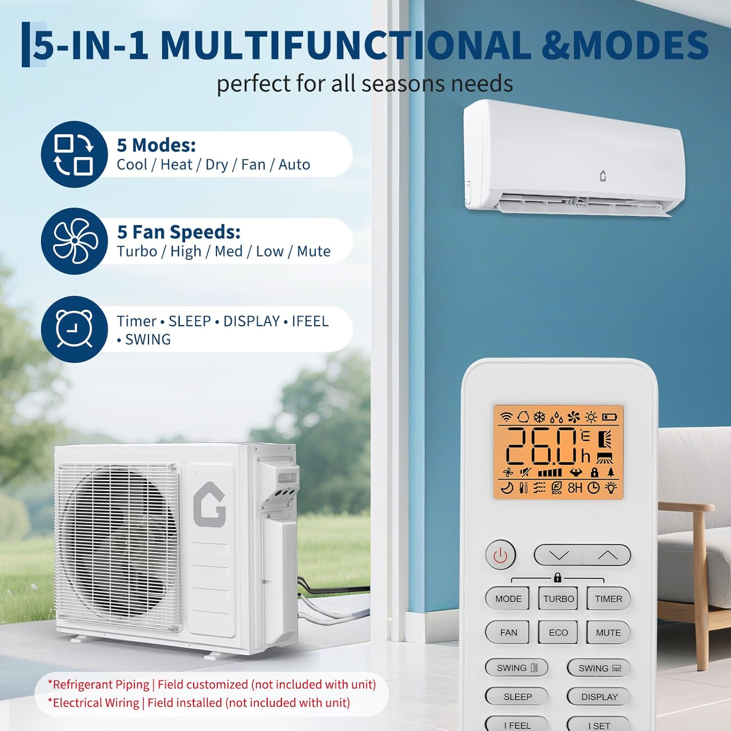
Figure 3.2: Indoor Unit with front panel open, revealing air filters.

Figure 3.3: Wireless Remote Control for adjusting settings.
Included Components:
- Outdoor Condenser Unit
- Two Indoor Air Handler Units (9,000 BTU each)
- Wireless Remote Controls (one for each indoor unit)
- User Manual (this document)
Note: Copper tubing and power cord are not included and must be sourced separately.
4. Specifications
| Feature | Specification |
|---|---|
| Brand | Garvee |
| Model Number | WY-_ZTaGifLdJViUlxc2P5qjQNzir39P |
| Capacity | 20,000 BTU (9K+9K Dual Zone) |
| Cooling Power | 20000 British Thermal Units |
| Seasonal Energy Efficiency Ratio (SEER2) | 20 |
| Voltage | 208-230V |
| Wattage | 1370.0 |
| Sound Level | 42 Decibels |
| Product Dimensions (Outdoor Unit) | 36.5"W x 27.52"D x 14.96"H |
| Product Dimensions (Indoor Unit 9K BTU) | 31.93"W x 11.5"D x 7.99"H |
| Item Weight | 152.1 pounds |
| Special Feature | Sleep Mode |
| Installation Method | Split System |
5. Setup and Installation
Professional HVAC installation is required for this system. The following steps provide an overview of the installation process. Refer to the detailed service manual for complete instructions.
5.1 Indoor Unit Installation
- Pre-installation Check: Before starting, check the status of both indoor and outdoor units. Verify no parts are broken, the indoor cross-fan operates, and the remote controller functions. If the cross-fan does not operate, check and adjust it first.
- Gas Flow Check: Verify there is no gas flow from the connector. If gas is detected, check the evaporator for any leakage.
- Electrical Wiring: Unfix the electric box cover. Connect the indoor and outdoor unit connection wires. Double-check the marks on the wires (1, 2, 3, and ground) to ensure correct and reliable wiring.
- Piping Direction: Based on the installation location, decide the piping direction and cut the face frame case accordingly. Ensure the cut edges are clean and smooth to prevent damage to the pipes.
- Connect Pipes: Adjust the connection pipes, paying attention to the alignment of the horn. Control the wrench's strength to prevent nut rupture. Ensure no gas leakage after pipe connection.
- Connect Drainage Pipe: Connect the drainage pipe. It must be sealed with electrical tape to ensure no water leakage.
- Wrap Pipes and Wires: Wrap the refrigerant pipes, drainage hose, and wiring together. Important: Retain the pipe connectors for later leak detection.
- Install Wall Plate: Install the wall plate, ensuring it is secure enough to hold the indoor unit.
- Mount Indoor Unit: Pass the pipes through the wall hole. Fix the indoor unit firmly on the mounting plate.
Video 5.1: Detailed installation steps for the indoor unit, including wiring and pipe connections. (Source: GarveeTech)
5.2 Outdoor Unit Installation
- Fix Outdoor Unit: Fix the outdoor unit on the mounting bracket. It is recommended to use rubbers on the feet to decrease possible vibration and noise.
- Open Refrigerant Pipes Cover: Open the refrigerant pipes cover on the outdoor unit.
- Connect Refrigerant Pipes: Connect the refrigerant pipes similar to the indoor unit. Control the force of the wrench to prevent nut breakage. Connect the pipe horn to the 2-way and 3-way valve straightly to prevent gas leakage.
- Electrical Connections: Open the electrical control box. The indoor and outdoor connection cable goes to the left hole of the cover, and the power cord to the right hole. Connect the indoor and outdoor connection wires to the electric terminal, paying attention to the marks of 1, 2, 3, and ground on the wires. They must be one-to-one correspondence with the markings on the terminal. Connect the power supply cable to the electric terminal. Ensure all wires are connected correctly and reliably.
Video 5.2: Detailed installation steps for the outdoor unit, including wiring and pipe connections. (Source: GarveeTech)
5.3 Vacuuming and Leakage Detection
- Connect Vacuum Pump: Connect one hose from the manifold low pressure gauge to the outdoor unit service port on the three-way valve. Then connect the manifold gauge to the vacuum pump.
- Vacuum System: Switch on the vacuum pump and open the gauge low pressure valve. For split AC, vacuum the unit for at least 15 minutes until the vacuum gauge is maintained at -14.5 psi. For R32 or R454B units, based on pipe length, vacuum for 15-30 minutes when pump capacity is 4-4.5 CFM.
- Pressure Hold Test: Close the low pressure valve on the manifold gauge, then switch off the vacuum pump. Hold the pressure for 5 minutes. Ensure the rebound of the compound gauge pointer does not exceed 0.73 psi. If it rebounds more than 0.73 psi, check and repair the leakage point, most likely from the pipe connector.
- Release Refrigerant: Open the outdoor unit low pressure valve counterclockwise for 1/4 turn with a hexagonal wrench to let a little refrigerant fill the system. Close the low pressure valve after 5 seconds. Check all pipe connectors of indoor and outdoor units for gas leakage. If leakage is found, repair and tighten the connection.
- Seal Wall Hole: Once no gas leakage is found, clean the connectors and wrap the indoor connector pipes. Seal the wall hole with sealing cement.
- Remove Pressure Hose: Keep the gauge at positive pressure and quickly remove the pressure hose from the outdoor unit service valve.
- Reinstall Protective Caps: Reinstall the protective caps of the service port, low pressure, and high pressure valves of the outdoor unit. Reinstall the valves cover.
Video 5.3: Vacuuming and leakage detection process for the mini split AC unit. (Source: GarveeTech)
6. Operating Instructions
After installation, switch on the unit for a running test. The system offers various modes for personalized comfort:
- Cool/Heat/Dry/Fan/Auto Modes: Select the desired operating mode.
- Fan Speeds: Choose from Turbo, High, Med, Low, or Mute fan speeds.
- Special Features: Utilize Sleep Mode, Silent Mode, Timer, I FEEL, I SET, and 8°C heating mode.
Wi-Fi & Voice Control: Each indoor unit has its own remote control, plus Wi-Fi and voice control (works with Alexa & Google Assistant). You can control the system from your smartphone, allowing you to set the temperature before you arrive home.

Figure 6.1: Smart control features via smartphone app and voice assistants.
Video 6.2: Instructions on how to connect the Dual Zone Mini Split Air Conditioner to Wi-Fi. (Source: GarveeTech)
7. Maintenance
Regular maintenance ensures the longevity and efficiency of your Garvee Mini Split system. Teach users how to use and normally maintain the air conditioner.
- Filter Cleaning: Regularly clean the air filters in the indoor units to maintain optimal airflow and air quality.
- Remote Control Batteries: Replace remote controller batteries as needed.
- General Inspection: Periodically check for any obstructions around the indoor and outdoor units.
8. Troubleshooting
If you encounter issues with your Garvee Mini Split system, consider the following general troubleshooting steps. For complex problems, contact a professional HVAC technician.
- No Power: Check the circuit breaker and ensure the unit is properly plugged in. Verify the separate leakage breaker is not tripped.
- Unit Not Cooling/Heating: Ensure the correct mode (Cool/Heat) is selected and the temperature setting is appropriate. Check for obstructions in the airflow.
- Remote Control Not Working: Replace batteries. Ensure there are no obstructions between the remote and the indoor unit.
- Unusual Noises: Minor noises during operation are normal. If loud or unusual noises occur, contact a technician.
- Water Leakage: Check the drainage pipe for blockages or improper installation. Ensure it is sealed correctly.
9. Warranty & Support
Your Garvee Mini Split AC/Heating System comes with a 30-day manufacturer's warranty. For warranty claims or technical support, please refer to the contact information provided with your purchase documentation.