1. Introduction
The PUSOKEI A78SD3 is a versatile computer motherboard designed to support AM3 interface APU processors and DDR3 memory. It offers robust performance and extensive connectivity for various computing needs, from gaming to multimedia tasks. This manual provides detailed instructions for installation, operation, and maintenance to ensure optimal performance and longevity of your motherboard.
Key features include:
- Strong Compatibility: Supports AM3 interface APU processors and dual-channel DDR3 memory up to 16GB (8GB per stick).
- High Definition Experience: Equipped with HDMI and VGA video outputs, 100Mbps Ethernet, and 5.1 channel sound for rich multimedia.
- Large Storage Capacity: Features 4 Serial ATA 3.0 ports for connecting multiple storage devices.
- Stable Performance: Multi-phase power design ensures stable operation and optimal performance.
- Versatile Interface Expansion: Includes 4 USB 2.0 ports and various headers for peripheral connectivity.
2. Technical Specifications
The following table details the technical specifications of the PUSOKEI A78SD3 Computer Motherboard:
| Feature | Specification |
|---|---|
| Item Type | A78SD3 Computer Motherboard |
| Material | PCB |
| Motherboard Chip | Integrated Sound Card, Network Card with Integrated Graphics |
| Main Chipset | for RS780 Series |
| Network Card Chip | Integrated 100Mbps Ethernet |
| Sound Chip | Integrated 6 Channel Sound Chip |
| Processor Support | Supports AM3 Interface for APU Processors |
| CPU Socket | AM3 |
| Memory Type | DDR3 1600/1333/1066MHz |
| Memory Slots | 2 x DDR3 (Max 16GB, 8GB per stick) |
| Expansion Slots | 1 x PCI-E X16 Graphics Card Slot, 1 x COM Serial Port Header, 2 x USB 2.0 Headers, 4 x Serial ATA 3.0 Ports |
| I/O Interfaces | PS/2 (Keyboard/Mouse), 1 x RJ45 Ethernet, 1 x VGA, 1 x HDMI, 4 x USB 2.0, Sound Interfaces |
| Motherboard Size | Approx. 17x21.3cm / 6.7x8.4in |
| Battery Type | 1 x CR2032L Battery (Included) |
| Power Connectors | 4 Pin and 24 Pin Power Connector |
| Power Supply Mode | 4 Phase |

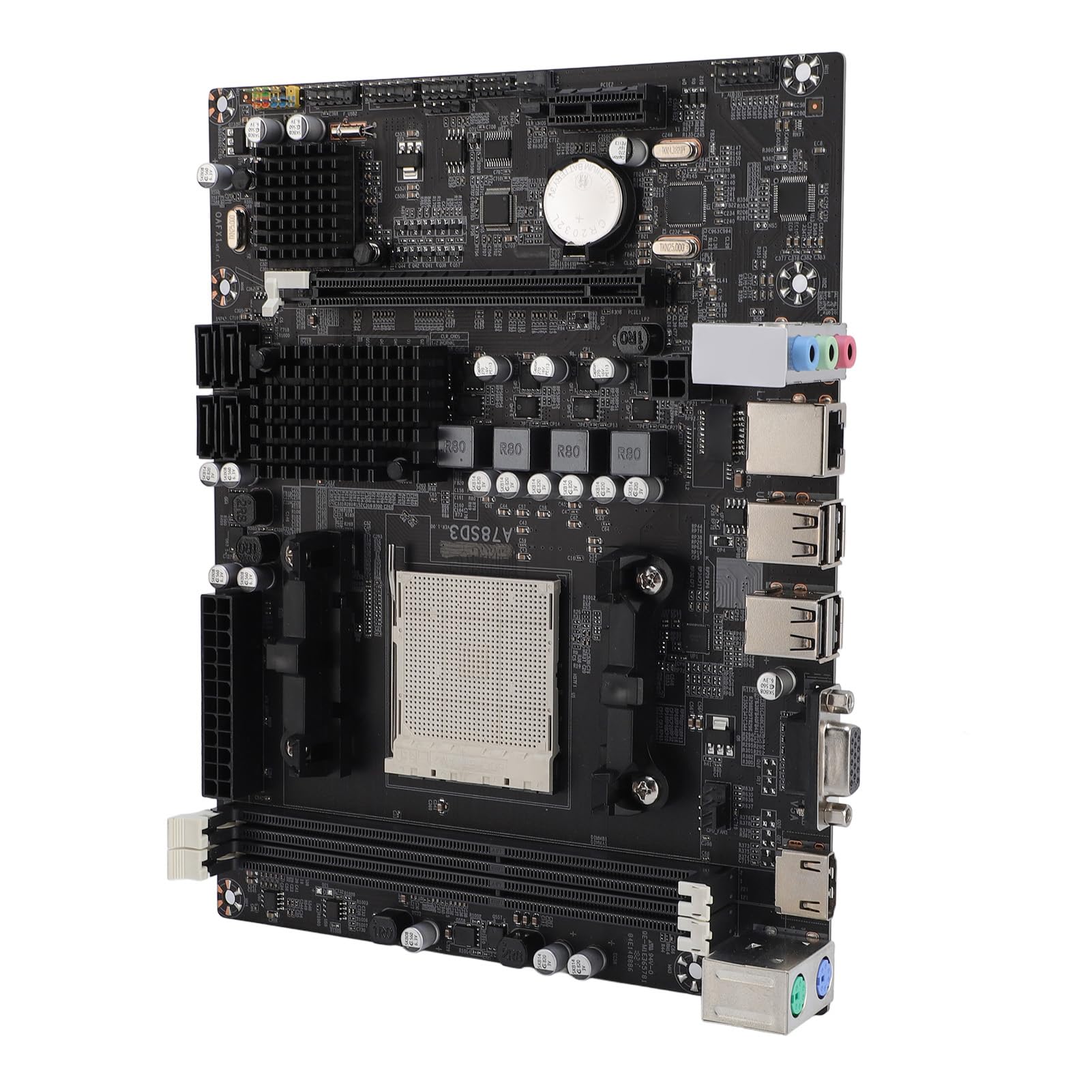
3. Component Overview
Familiarize yourself with the various components and connectors on the A78SD3 motherboard using the diagram below:

- CPU Socket (AM3): For installing compatible AMD AM3 series processors.
- DDR3 Memory Slots: Two slots for DDR3 RAM modules.
- PCIe X16 Slot: For installing a dedicated graphics card.
- SATA 3.0 Ports: Four ports for connecting storage devices like HDDs and SSDs.
- 24-pin ATX Power Connector: Main power input from the power supply unit (PSU).
- 4-pin CPU Power Connector: Provides additional power to the CPU.
- I/O Panel: Includes PS/2 ports, USB 2.0 ports, RJ45 Ethernet, VGA, HDMI, and audio jacks.
- USB 2.0 Headers: For connecting front panel USB ports or other internal USB devices.
- COM Serial Port Header: For legacy serial port connections.
4. Installation and Setup
This section guides you through the process of installing your PUSOKEI A78SD3 motherboard and its components.
4.1 Unpacking
Carefully unpack the motherboard and check the contents against the packing list:
- 1 x A78SD3 Computer Motherboard
- 1 x I/O Baffle
- 1 x Serial ATA Cable
- 1 x User Manual (this document)

4.2 Motherboard Installation
Follow these steps for proper installation:
- Prepare the Case: Ensure your computer case is ready, with standoffs correctly aligned for the motherboard.
- Install I/O Shield: Snap the I/O shield (baffle) into the corresponding opening at the rear of your computer case.
- Install CPU:
- Open the CPU socket lever.
- Carefully align the CPU with the socket, ensuring the triangular mark on the CPU matches the mark on the socket. Do not force the CPU into place.
- Gently lower the CPU into the socket.
- Close the socket lever to secure the CPU.

Figure 4.2: Close-up of the AM3 CPU socket on the A78SD3 motherboard, ready for processor installation. - Install CPU Cooler: Apply thermal paste (if not pre-applied) and install the CPU cooler according to its manufacturer's instructions. Connect the CPU fan cable to the CPU_FAN header on the motherboard.
- Install RAM:
- Open the clips on both ends of the DDR3 memory slots.
- Align the notch on the RAM module with the notch in the memory slot.
- Press down firmly on both ends of the RAM module until the clips snap into place.

Figure 4.3: Close-up of the two DDR3 memory slots on the A78SD3 motherboard, indicating where RAM modules are to be installed. - Mount Motherboard: Carefully place the motherboard into the case, aligning the screw holes with the standoffs. Secure it with screws.
- Connect Power: Connect the 24-pin ATX power connector and the 4-pin CPU power connector from your PSU to the motherboard.
- Install Graphics Card (Optional): If using a dedicated graphics card, insert it into the PCIe X16 slot until it clicks into place. Secure it with a screw to the case. Connect any required PCIe power cables from the PSU to the graphics card.
- Connect Storage Devices: Use the provided Serial ATA cable to connect your SSDs/HDDs to the SATA 3.0 ports on the motherboard. Connect power cables from the PSU to your storage devices.
- Connect Front Panel Cables: Connect the power button, reset button, HDD LED, power LED, and front panel USB/audio cables to their respective headers on the motherboard. Refer to the motherboard diagram (Figure 3.1) and your case manual for correct pin assignments.
- Connect Peripherals: Connect your monitor, keyboard, mouse, and other peripherals to the I/O panel ports.
5. Operation
Once all components are installed and connected, you can power on your system.
- Initial Boot: Press the power button on your computer case. The system should power on, and you should see a display on your monitor.
- BIOS/UEFI Setup: During the initial boot sequence, you may need to press a specific key (commonly Del, F2, F10, or F12) to enter the BIOS/UEFI setup utility. Here, you can configure boot order, system time, and other advanced settings.
- Operating System Installation: If you are building a new system, you will need to install an operating system (e.g., Windows, Linux) from a bootable USB drive or DVD.
- Driver Installation: After installing the operating system, install the necessary drivers for the motherboard's chipset, integrated graphics (if used), network, and audio. These are typically provided on a CD/DVD with the motherboard or can be downloaded from the PUSOKEI website.
6. Maintenance and Care
Proper maintenance ensures the longevity and stable performance of your motherboard.
- Keep it Clean: Regularly clean dust from inside your computer case using compressed air. Dust can accumulate on components and lead to overheating.
- Environmental Conditions: Operate the motherboard in a well-ventilated area with stable temperature and humidity. Avoid extreme temperatures and direct sunlight.
- Handle with Care: Always handle the motherboard by its edges to avoid touching sensitive components or static discharge. Use an anti-static wrist strap when working inside your computer.
- BIOS Updates: Periodically check the PUSOKEI website for BIOS updates. Updates can improve stability, compatibility, and performance. Follow update instructions carefully.
- Cable Management: Ensure cables inside the case are neatly managed to improve airflow and prevent interference.
7. Troubleshooting
If you encounter issues with your motherboard, refer to the following common troubleshooting steps:
- No Power:
- Check if the PSU is switched on and all power cables (24-pin ATX, 4-pin CPU) are securely connected.
- Ensure the front panel power button cable is correctly connected to the motherboard header.
- No Display:
- Verify that the monitor is connected to the correct video output (motherboard's VGA/HDMI or dedicated graphics card).
- Reseat the RAM modules. Try booting with only one RAM stick.
- If using a dedicated graphics card, ensure it is properly seated and has power.
- Clear CMOS (refer to motherboard manual for jumper location or remove/reinsert the CR2032L battery).
- System Instability/Crashes:
- Check CPU and GPU temperatures. Ensure coolers are properly installed and fans are spinning.
- Run memory diagnostic tools to check for faulty RAM.
- Ensure all drivers are up to date.
- Check PSU wattage; it might be insufficient for your components.
- Peripheral Not Detected:
- Try connecting the peripheral to a different port.
- Ensure the peripheral's drivers are installed.
- Check BIOS settings to ensure the port is enabled.
8. Warranty and Support
For warranty information and technical support, please refer to the official PUSOKEI website or contact your retailer. Keep your proof of purchase for warranty claims.