1. Introduction
This manual provides detailed instructions for the installation, configuration, and operation of your ASRock X870 Taichi Creator Motherboard. This high-performance ATX motherboard is designed to support AMD Ryzen 9000, 8000, and 7000 Series Processors with an AM5 socket, offering advanced features for creators and enthusiasts.
2. Safety Information
Please read the following safety guidelines carefully before installing or operating your motherboard to prevent damage to the product or injury to yourself.
- Always disconnect the power cord from the wall outlet before touching any components.
- Wear an anti-static wrist strap to prevent electrostatic discharge (ESD) when handling components.
- Ensure proper ventilation within your PC case to prevent overheating.
- Keep the motherboard away from moisture and extreme temperatures.
- Refer to the CPU and other component manuals for specific installation instructions.
3. Package Contents
Verify that all items listed below are present in your motherboard package. If any item is missing or damaged, contact your retailer.
- ASRock X870 Taichi Creator Motherboard
- Quick Installation Guide
- Regulatory Notice
- SATA Data Cables
- Wi-Fi Antenna
- M.2 Screws and Standoffs
- ASRock Graphics Card Holder
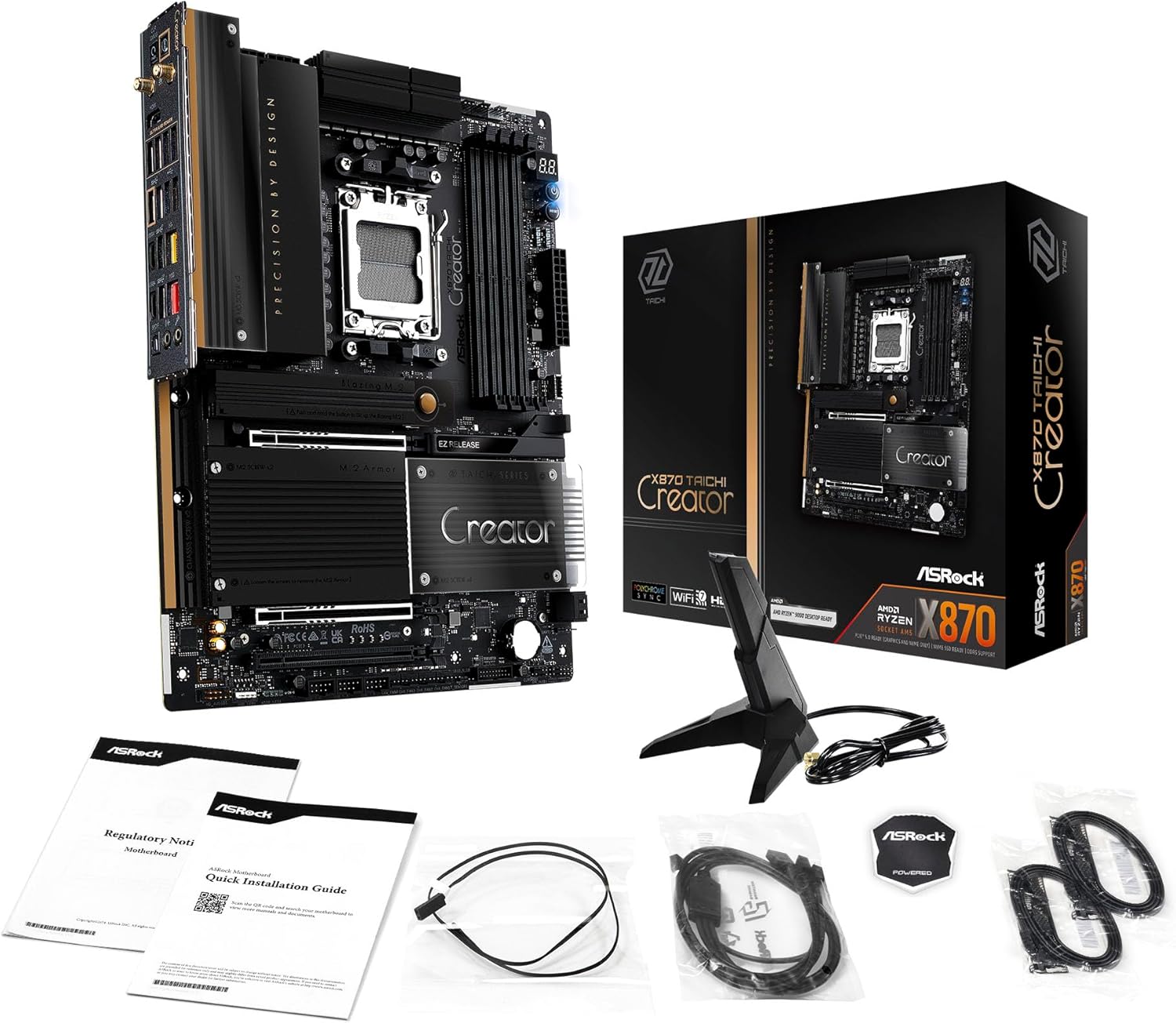
Image: The ASRock X870 Taichi Creator Motherboard shown alongside its retail packaging and various accessories, including cables, documentation, and a graphics card holder.
4. Setup and Installation
Follow these steps for proper installation of your motherboard and its components.
4.1. CPU Installation (Socket AM5)
- Locate the AM5 CPU socket on the motherboard.
- Gently lift the CPU retention lever.
- Align the triangular mark on your AMD Ryzen processor with the corresponding mark on the socket.
- Carefully place the CPU into the socket without applying force.
- Lower the retention lever until it clicks into place, securing the CPU.

Image: A top-down view of the ASRock X870 Taichi Creator Motherboard, highlighting the central AM5 CPU socket and surrounding components like VRMs and RAM slots.
4.2. Memory (RAM) Installation
The motherboard supports 4 x DDR5 DIMM slots for dual-channel memory technology.
- Open the clips at both ends of the DIMM slot.
- Align the notch on the DDR5 memory module with the key in the DIMM slot.
- Insert the memory module firmly into the slot until the clips snap into place.
- For dual-channel configuration, refer to your motherboard manual for recommended slot pairing.
4.3. Storage Device Installation
The motherboard features M.2 slots and SATA3 ports for storage.
4.3.1. M.2 SSD Installation
The board includes 1 Ultra M.2 (PCIe Gen3x4), 1 Hyper M.2 (PCIe Gen4x4), and 2 Blazing M.2 (PCIe Gen5x4) slots.
- Locate the desired M.2 slot and remove the M.2 heatsink if present.
- Insert the M.2 SSD into the slot at a 30-degree angle.
- Gently push down the SSD and secure it with the provided M.2 screw or standoff.
- Reattach the M.2 heatsink for optimal thermal performance.
4.3.2. SATA Device Installation
Connect SATA storage devices (HDDs/SSDs) to the 4 SATA3 ports using SATA data cables.
4.4. PCIe Card Installation
The motherboard provides 2 PCIe 5.0 x16 (x8/x8) slots and 1 PCIe 3.0 x16 slot.
- Select an available PCIe slot.
- Remove the corresponding expansion slot cover from your PC case.
- Align your PCIe card with the slot and press down firmly until it is seated correctly.
- Secure the card with a screw to the PC case.
4.5. Power Connections
Connect the 24-pin ATX power connector and the 8-pin (or 4+4-pin) CPU power connector from your power supply unit (PSU) to the corresponding ports on the motherboard.
4.6. Front Panel and Rear I/O Connections
Connect your PC case's front panel connectors (power button, reset button, USB ports, audio jacks) to the appropriate headers on the motherboard. Connect peripherals to the rear I/O panel.

Image: A close-up view of the rear I/O panel of the ASRock X870 Taichi Creator Motherboard, showing various ports including USB, HDMI, Ethernet, and audio jacks.
5. Operating Instructions
5.1. Initial Boot and BIOS/UEFI Setup
- After assembling your PC, connect a monitor, keyboard, and mouse.
- Power on your system. During startup, repeatedly press the Del or F2 key to enter the BIOS/UEFI setup utility.
- Configure boot order, enable XMP/EXPO for memory, and adjust other settings as needed.
- Save changes and exit the BIOS/UEFI. The system will restart.
5.2. Driver Installation
After installing your operating system, install the necessary drivers for the motherboard components. These can typically be found on the ASRock support website or the included driver CD/USB drive.
- Chipset Drivers
- LAN Drivers (10Gbps, 5Gbps)
- Wi-Fi 7 + Bluetooth Drivers
- Audio Drivers (Realtek ALC4082)
- USB Drivers
6. Maintenance
6.1. Cleaning
Regularly clean your PC to prevent dust buildup, which can lead to overheating. Use compressed air to remove dust from fans, heatsinks, and other components. Ensure the system is powered off and unplugged before cleaning.
6.2. BIOS Updates
Periodically check the ASRock website for BIOS/UEFI updates. Updates can improve system stability, add support for new CPUs, or fix bugs. Follow the instructions provided by ASRock carefully when performing a BIOS update.
7. Troubleshooting
If you encounter issues, refer to the following common troubleshooting steps:
- No Power: Ensure all power cables (24-pin ATX, 8-pin CPU) are securely connected. Check your PSU and wall outlet.
- No Display: Verify that your monitor is connected to the correct graphics output (dedicated GPU or integrated graphics). Reseat your graphics card and RAM modules.
- System Instability: Check CPU and GPU temperatures. Ensure RAM is properly seated and configured (XMP/EXPO settings). Update drivers and BIOS.
- BIOS Flashback: The motherboard features a BIOS Flashback button on the rear I/O panel. This allows you to update the BIOS without a CPU or RAM installed. Refer to the ASRock website for detailed instructions on using this feature.
- Clear CMOS: If your system fails to boot after changing BIOS settings, you can clear the CMOS to reset BIOS settings to default. Locate the 'CLR CMOS' button or jumper on the motherboard (often near the rear I/O).
8. Specifications
| Feature | Specification |
|---|---|
| Brand | ASRock |
| Model Name | X870 |
| Item Model Number | 90-MXBTE0-A0UAYZ |
| CPU Socket | Socket AM5 |
| Compatible Processors | AMD Ryzen 9000, AMD Ryzen 8000, AMD Ryzen 7000 Series |
| Chipset Type | AMD X870 |
| RAM Memory Technology | DDR5 |
| Memory Slots | 4 x DDR5 DIMM Slots (Dual Channel, up to 8000+(OC), 256GB max) |
| Graphics Output | 2 x USB4 Type-C (up to 8K 30Hz), 1 x HDMI 2.1 (up to 4K 120Hz) |
| PCIe Slots | 2 x PCIe 5.0 x16 (x8/x8), 1 x PCIe 3.0 x16 |
| Storage | 4 x SATA3, 1 x Ultra M.2 (PCIe Gen3x4), 1 x Hyper M.2 (PCIe Gen4x4), 2 x Blazing M.2 (PCIe Gen5x4) |
| LAN | 10Gbps LAN, 5Gbps LAN |
| Wireless LAN | 802.11be Wi-Fi 7 + Bluetooth |
| Audio | Realtek ALC4082 7.1 CH HD Audio Codec, Nahimic Audio |
| USB Ports (Rear) | 2 x USB 2.0, 6 x USB 3.2 Gen1, 2 x USB 3.2 Gen2, 2 x USB4 Type-C |
| USB Ports (Front) | 6 x USB 2.0, 4 x USB 3.2 Gen1, 1 x USB 3.2 Gen2x2 Type-C |
| Form Factor | ATX |
| Power Phase Design | 18+2+1 Power Phase, 80A SPS |
9. Warranty Information
ASRock motherboards typically come with a limited manufacturer's warranty. The duration and terms of the warranty may vary by region and retailer. Please retain your proof of purchase for warranty claims. For detailed warranty information, refer to the official ASRock website or contact your point of purchase.
10. Technical Support
For technical assistance, driver downloads, BIOS updates, and further product information, please visit the official ASRock support website:
You may also contact ASRock customer service directly through their website for personalized support.


