
1. Introduction
This manual provides detailed instructions for the safe and effective operation of your MESTEK CM83E Digital Clamp Meter Multimeter. This True-RMS 6000 counts auto-ranging device is designed for measuring AC/DC current, AC/DC voltage, temperature, capacitance, resistance, continuity, diode, and Non-Contact Voltage (NCV). It is a versatile tool for electrical troubleshooting in various applications.
Package Contents:
- 1 x MESTEK CM83E Clamp Meter
- 1 x Temperature Probe (Thermocouple)
- 1 x Pair of Test Leads
- 2 x 1.5V AAA Batteries
- 1 x Screwdriver
- 1 x Multimeter Hard Case
- 1 x User Manual (this document)

Image 1.1: MESTEK CM83E Digital Clamp Meter with included test leads, temperature probe, batteries, screwdriver, and hard case.
2. Safety Information
Always adhere to safety precautions when using electrical testing equipment. Failure to do so may result in injury or damage to the device.
- This device complies with safety standard IEC 61010-1, CAT III 600V.
- Ensure the meter is in the correct function mode before making any measurements.
- Do not attempt to measure voltages or currents exceeding the specified maximum limits.
- Always inspect test leads for damage before use. Replace damaged leads immediately.
- Exercise caution when working with live circuits. Avoid contact with bare wires or terminals.
- Do not operate the meter if it appears damaged or if the battery cover is not properly closed.
- Remove test leads from the circuit before changing functions.
- When measuring current with the clamp, ensure only one conductor is within the jaw. Clamping around multiple conductors will result in an inaccurate reading.
3. Product Overview
Familiarize yourself with the components of the MESTEK CM83E Digital Clamp Meter.
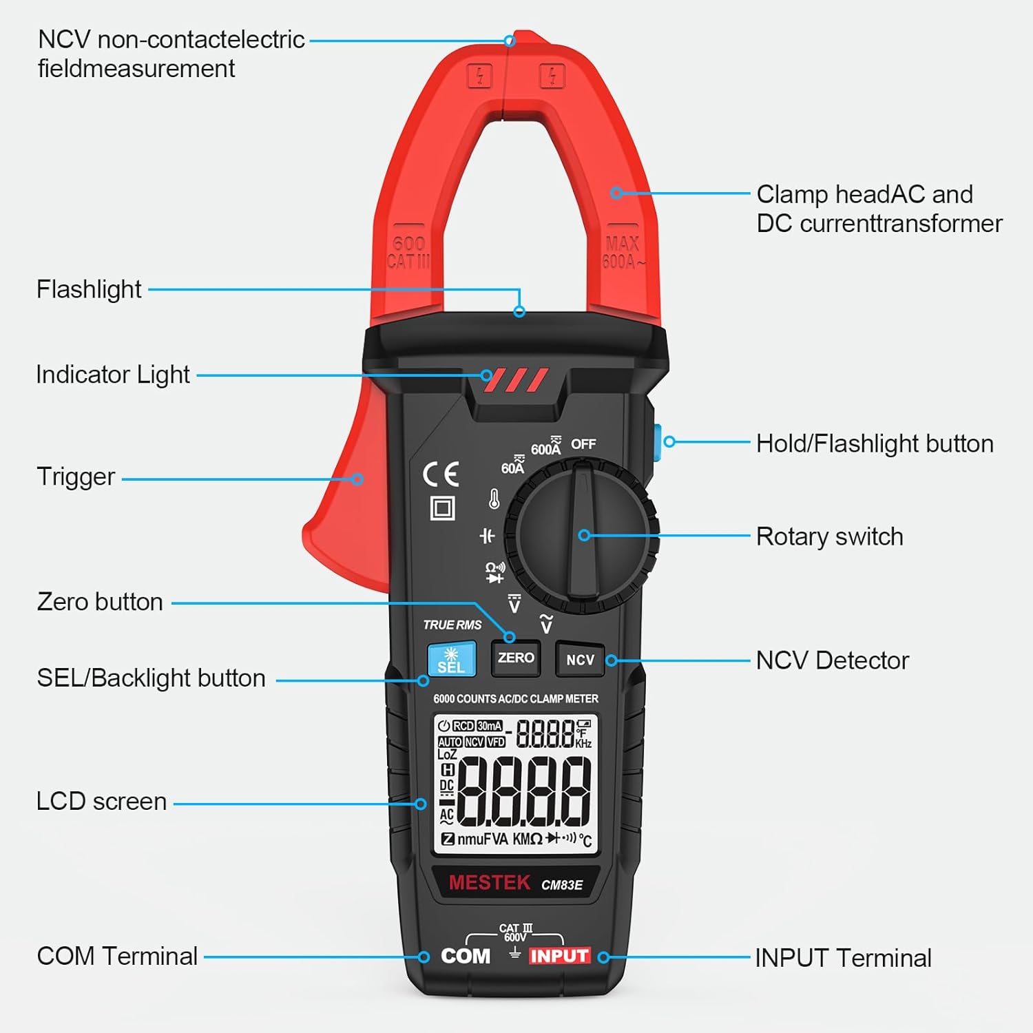
Image 3.1: Labeled components of the MESTEK CM83E Clamp Meter.
- NCV Non-Contact Electric Field Measurement: Detects AC voltage without physical contact.
- Clamp Head (AC and DC Current Transformer): Used for non-contact current measurement.
- Flashlight: Illuminates the work area.
- Indicator Light: Provides visual feedback, especially for NCV.
- Trigger: Opens the clamp jaw.
- Zero Button: Used to zero out readings for DC current measurements.
- SEL/Backlight Button: Selects sub-functions within a rotary switch position and activates the backlight.
- LCD Screen: Displays measurement readings and indicators.
- COM Terminal: Common input terminal for test leads (black lead).
- INPUT Terminal: Positive input terminal for test leads (red lead).
- NCV Detector: Sensor for non-contact voltage detection.
- Rotary Switch: Selects the desired measurement function.
- Hold/Flashlight Button: Freezes the current display reading and activates the flashlight.
4. Setup
4.1 Battery Installation
The MESTEK CM83E requires two 1.5V AAA batteries. These are included in your package.
- Locate the battery compartment on the back of the meter.
- Use the included screwdriver to open the battery compartment cover.
- Insert the two AAA batteries, observing the correct polarity (+ and -).
- Replace the battery compartment cover and secure it with the screw.
4.2 Connecting Test Leads
For most measurements (voltage, resistance, capacitance, diode, continuity), the test leads must be connected.
- Insert the black test lead into the COM (Common) input terminal.
- Insert the red test lead into the INPUT terminal.
Note: Always remove the protective caps from the test leads before use.
5. Operating Instructions
Turn the rotary switch to the desired function to begin measurements.

Image 5.1: Overview of multi-function capabilities including voltage, current, temperature, capacitance, diode, continuity, NCV, zero, and flashlight.
5.1 AC/DC Current Measurement (Clamp)
Use the clamp jaw to measure AC or DC current without breaking the circuit.
- Turn the rotary switch to the 600A AC/DC Current position.
- Press the trigger to open the clamp jaw.
- Enclose only one conductor within the clamp jaw. Do not clamp around an entire power cord (which contains both live and neutral wires), as this will result in a zero reading.
- Read the current value on the LCD screen. For DC current, press the ZERO button to eliminate any offset before measurement.
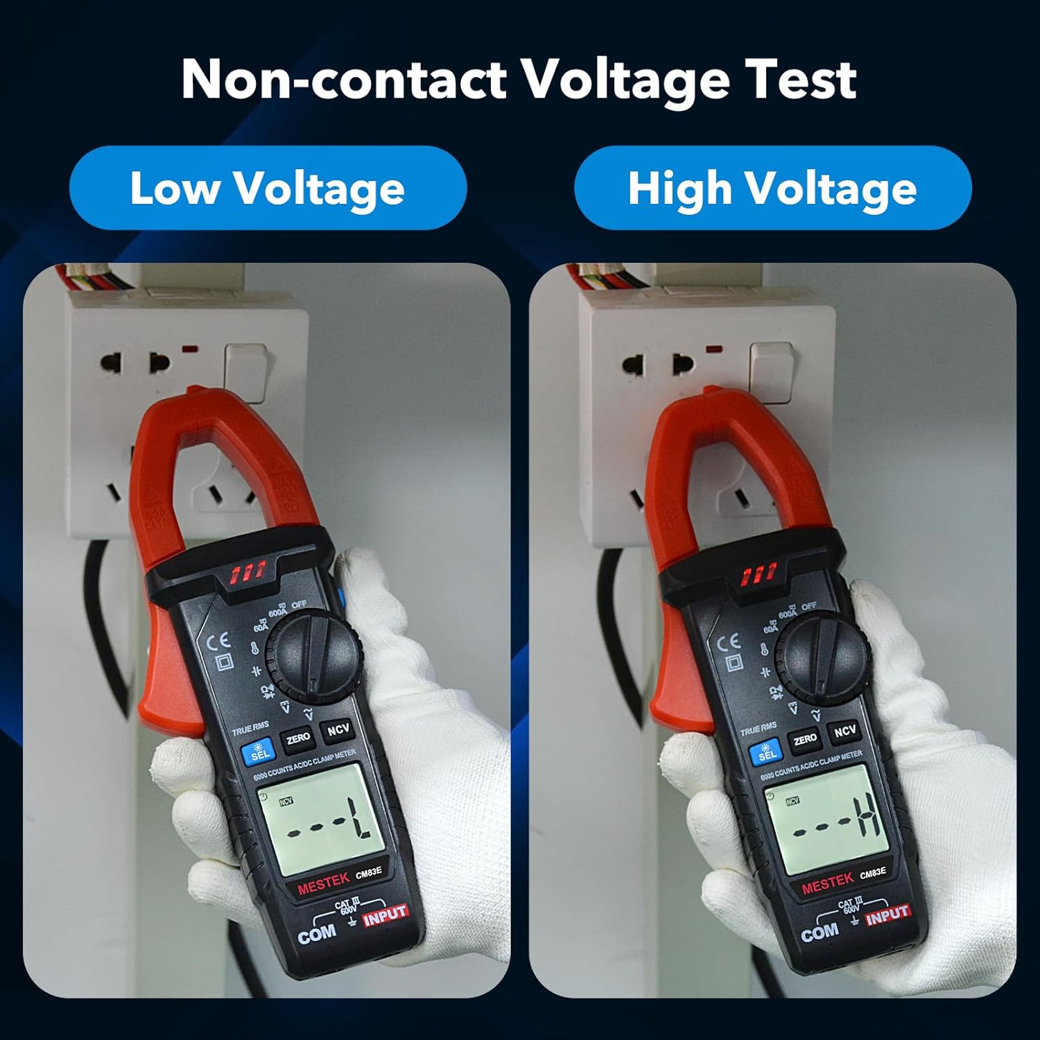
Image 5.2: Measuring AC/DC Current.

Image 5.3: Correct (right) vs. Incorrect (left) Current Measurement.
5.2 AC/DC Voltage Measurement
Use the test leads to measure AC or DC voltage.
- Turn the rotary switch to the V~ (AC Voltage) or V- (DC Voltage) position. The meter will auto-range.
- Connect the test leads in parallel to the circuit or component being measured.
- Read the voltage value on the LCD screen.

Image 5.4: Measuring AC/DC Voltage.
5.3 Resistance, Capacitance, Diode, and Continuity Measurement
These functions are typically grouped on the rotary switch. Use the SEL button to cycle through them.
- Turn the rotary switch to the position indicating these functions (e.g., Ω, †, ♫).
- Press the SEL button to select the desired function (Resistance Ω, Diode †, or Continuity ♫).
- Connect the test leads across the component to be measured.
- For continuity, a beep indicates a continuous circuit. For diode, the forward voltage drop is displayed.

Image 5.5: Continuity, Diode, and Capacitance Measurement.
5.4 Temperature Measurement
Use the included K-type thermocouple for temperature readings.
- Turn the rotary switch to the ℃/℉ position.
- Insert the thermocouple into the INPUT and COM terminals, observing polarity.
- Place the thermocouple tip on or near the object whose temperature is to be measured.
- Read the temperature on the LCD screen.

Image 5.6: Temperature Measurement using K-type Thermocouple.
5.5 Non-Contact Voltage (NCV) Test
Detect AC voltage without direct contact with conductors.
- Turn the rotary switch to the NCV position.
- Move the NCV detector (top part of the clamp head) close to the conductor or outlet.
- The indicator light will flash and an audible alarm will sound, with increasing frequency as the voltage strength increases. The LCD will display '----' for low voltage and 'H' for high voltage.

Image 5.7: Non-Contact Voltage (NCV) Test.
5.6 Data Hold Function
To freeze the current reading on the display:
- Press the HOLD button during a measurement. The reading will be held on the screen.
- Press the HOLD button again to release the reading and return to live measurement.

Image 5.8: Data Hold Function.
5.7 Backlight and Flashlight
For working in dimly lit conditions:
- Press the SEL button for approximately 2 seconds to turn on the LCD backlight. Press again for 2 seconds to turn it off.
- Press the HOLD/Flashlight button for approximately 2 seconds to turn on the flashlight. Press again for 2 seconds to turn it off.
Image 5.9: Using the Backlight and Flashlight in low-light conditions.
5.8 Auto Power Off
The meter will automatically power off after approximately 10 minutes of inactivity to conserve battery life.
6. Maintenance and Care
- Cleaning: Wipe the meter with a damp cloth and mild detergent. Do not use abrasives or solvents.
- Battery Replacement: When the low battery indicator appears on the LCD, replace the batteries promptly to ensure accurate readings. Refer to Section 4.1 for battery installation instructions.
- Storage: If the meter is not used for an extended period, remove the batteries to prevent leakage. Store the meter in its hard case in a cool, dry place.
- Calibration: For professional use, periodic calibration by a qualified technician is recommended to maintain accuracy.
7. Troubleshooting
If you encounter issues with your MESTEK CM83E, consider the following common solutions:
- No Display/Meter Not Turning On: Check battery installation and ensure batteries are not depleted. Replace if necessary.
- Inaccurate Readings:
- Ensure test leads are fully inserted and not damaged.
- Verify the rotary switch is set to the correct function.
- For current measurement, ensure only one conductor is within the clamp jaw.
- For DC current, use the ZERO function to compensate for residual magnetism.
- Continuity Test Not Beeping: Ensure the circuit is de-energized and there is a complete path for current flow.
- NCV Not Detecting Voltage: Ensure the NCV sensor is close enough to the AC voltage source.
If problems persist, contact MESTEK customer service for further assistance.
8. Specifications
| Feature | Specification |
|---|---|
| Model Number | CM83E |
| AC/DC Current | Max 600A |
| AC/DC Voltage | Max 600V |
| Display Counts | 6000 Counts |
| True RMS | Yes |
| Measurement Functions | Current, Voltage, Temperature, Capacitance, Resistance, Continuity, Diode, NCV |
| Safety Rating | CAT III 600V |
| Power Source | 2 x 1.5V AAA Batteries (included) |
| Auto Power Off | After 10 minutes of inactivity |
| Product Dimensions | 7.9 x 3 x 1.5 inches |
| Item Weight | 0.47 Pounds (7.52 ounces) |
| Jaw Opening | 1.37 inches (35mm) |

Image 8.1: MESTEK CM83E Clamp Meter Dimensions.
9. Warranty and Support
MESTEK provides comprehensive customer support for your CM83E Digital Clamp Meter.
- Warranty: The product includes a 24-month after-sale service warranty.
- Technical Support: 7/24 customer service and technical support are available.
- Replacement Policy: If the clamp meter is damaged within 24 months of purchase, contact MESTEK for a replacement.
For assistance, please refer to the contact information provided with your purchase or visit the official MESTEK website.