1. Introduction
Thank you for choosing the YESWELDER FLUX-135 MINI 3-in-1 Welding Machine. This manual provides essential information for the safe and efficient operation, setup, and maintenance of your new welding equipment. Please read this manual thoroughly before operating the machine to ensure proper use and to prevent injury or damage.
The YESWELDER FLUX-135 MINI is a versatile welding machine designed for Flux Core, Lift TIG, and Stick welding processes, suitable for various applications from automotive to DIY projects.
2. Safety Instructions
WARNING: Welding can be dangerous. Always follow safety precautions to prevent serious injury or death.
- Electric Shock: Can kill. Do not touch live electrical parts. Wear dry welding gloves and protective clothing. Ensure the work area is dry.
- Fumes and Gases: Can be hazardous to your health. Keep your head out of the fumes. Use ventilation or exhaust to remove fumes from the breathing zone.
- Arc Rays: Can injure eyes and burn skin. Wear a welding helmet with a proper shade filter. Wear protective clothing to cover all exposed skin.
- Fire and Explosion: Welding sparks can cause fire or explosion. Keep flammable materials away from the welding area. Have a fire extinguisher readily available.
- Hot Parts: Can cause severe burns. Allow equipment to cool before touching.
- Machine Safety Features: This unit includes automatic compensation for voltage fluctuation and robust protections against over-current, over-load, and over-heating. However, these features do not replace safe operating practices.
Always refer to national and local safety standards for welding operations.
3. Product Overview
3.1 Key Features
- Multi-Process Capability: 3-in-1 functionality for Flux Core, Lift TIG, and Stick welding.
- Welding Capacity: 135A output, 110V input, suitable for various light to medium duty welding tasks.
- Synergic MIG Mode: Automatically matches voltage to wire feeding speed, with fine-tuning capability (-3V to +3V). Ideal for beginners.
- Manual MIG Mode: Allows experienced users to manually adjust wire feeding speed and voltage.
- Digital Display: Provides clear monitoring of operational parameters for enhanced control.
- Safety Protections: Includes safeguards against over-current, over-load, over-heating, and automatic voltage fluctuation compensation.
3.2 Components and Controls
The YESWELDER FLUX-135 MINI welding machine features a compact design with an intuitive control panel and essential connections.

Figure 1: YESWELDER FLUX-135 MINI Welding Machine with included Lift TIG Torch and accessories. This image shows the compact size and the various connections on the front panel.
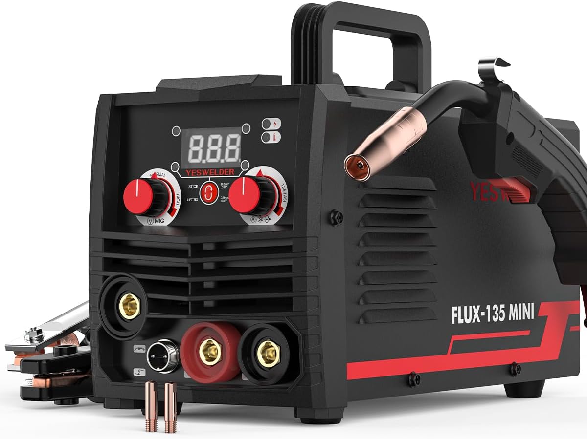
Figure 2: Front view of the YESWELDER FLUX-135 MINI, highlighting the MIG gun connection and the main control panel with digital display and adjustment knobs.

Figure 3: Detailed view of the control panel, showing the digital display for current/voltage, mode selection switch (MIG, STICK, LIFT TIG), and adjustment knobs for welding parameters. The panel is designed for simple and efficient operation.
Front Panel Controls:
- Digital Display: Shows welding current, voltage, or other selected parameters.
- Mode Selector: Switch to select between MIG (Flux Core), Stick, and Lift TIG welding modes.
- Current/Wire Speed Knob: Adjusts welding current in Stick/TIG mode or wire feed speed in MIG mode.
- Voltage Adjustment Knob: Fine-tunes voltage in MIG mode (Synergic or Manual).
- Output Terminals: Connections for welding cables (positive and negative).
- MIG Gun Connection: For connecting the MIG torch.
- TIG Torch Connection: For connecting the Lift TIG torch.
Rear Panel:
- Power Input: For connecting the 110V power cord.
- Cooling Fan: Ensures proper ventilation and prevents overheating.
4. Setup
4.1 Power Connection
- Ensure the welding machine's power switch is in the OFF position.
- Connect the power cord to a grounded 110V AC power outlet. Ensure the outlet can provide sufficient amperage for the welder's maximum output.
4.2 Wire Spool Installation (Flux Core MIG)

Figure 4: Illustration of a 2LB flux cored welding wire spool being installed into the wire feeder compartment of a welding machine. The image emphasizes compatibility with 2LB spools (4" diameter).
- Open the wire feeder compartment cover.
- Place the 2LB (4-inch diameter) flux core wire spool onto the spool holder. Ensure the wire unwinds from the bottom.
- Thread the wire through the guide tube and into the drive roller mechanism.
- Close the drive roller tension arm and adjust the tension. The wire should feed smoothly without slipping or deforming.
- With the MIG gun pointed away from yourself and others, press the trigger to feed the wire through the MIG gun liner until it exits the contact tip.
- Trim the wire to approximately 1/2 inch (12-15mm) stick-out.
Compatible Wire Sizes: .023" (0.6mm), .030" (0.8mm), .035" (0.9mm) flux core wire.
4.3 Connecting Welding Accessories
- Ground Clamp: Connect the ground clamp cable to the appropriate output terminal (usually negative for Flux Core MIG). Secure the clamp to the workpiece or welding table, ensuring good electrical contact.
- MIG Gun: Connect the MIG gun cable to the MIG gun connection port on the front panel.
- Lift TIG Torch: For Lift TIG welding, connect the TIG torch to its designated port and the ground clamp to the appropriate terminal (usually positive for DC TIG, check specific polarity requirements for your application).
- Stick Electrode Holder: For Stick welding, connect the electrode holder cable to the appropriate output terminal (polarity depends on electrode type) and the ground clamp to the other terminal.
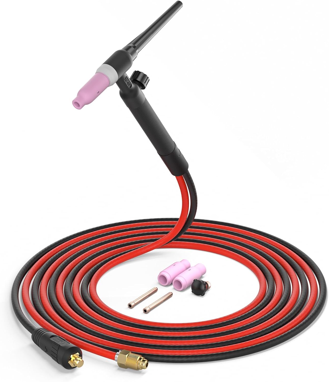
Figure 5: The Lift TIG torch with its cable and various consumables (collets, ceramic cups) ready for connection to the welding machine. This image shows the complete TIG torch assembly.

Figure 6: A selection of TIG torch accessories, including different sizes of alumina ceramic cups (#4, #5, #6), collet bodies (1/8"), collets (3/23", 1/16", .078"), and short/long back caps. These are essential for various TIG welding applications.
5. Operating Instructions
5.1 General Operation Steps
- Ensure all connections are secure and correct for the chosen welding process.
- Turn on the welding machine using the power switch. The digital display will illuminate.
- Select the desired welding mode (MIG, STICK, or LIFT TIG) using the mode selector switch.
- Adjust welding parameters (current, voltage, wire speed) according to the material thickness and welding process. Refer to welding charts or practice on scrap material.
- Wear all necessary Personal Protective Equipment (PPE) including welding helmet, gloves, and protective clothing.
- Begin welding.
- After welding, turn off the machine and allow it to cool.
5.2 Flux Core MIG Welding

Figure 7: An illustration showing Flux Cored Welding in action, demonstrating the arc and molten puddle. This image is part of a "3-IN-1 Multi-function welding machine" graphic.
Flux Core MIG welding uses a continuously fed tubular wire containing flux, eliminating the need for external shielding gas. This mode is suitable for outdoor use and on dirty or rusty materials.
- Select "MIG" mode.
- Synergic Control: Adjust the wire feeding speed knob. The machine will automatically suggest a corresponding voltage. You can fine-tune this voltage using the voltage adjustment knob (-3V to +3V).
- Manual Control: For experienced users, manually set both wire feeding speed and voltage.
- Ensure correct polarity (typically DCEN - Direct Current Electrode Negative for flux core).
- Maintain a consistent stick-out and travel speed for optimal results.
5.3 Lift TIG Welding
Lift TIG welding provides precise control and high-quality welds, especially on thinner materials. This machine uses a Lift TIG start, which minimizes tungsten contamination.
- Select "LIFT TIG" mode.
- Connect the Lift TIG torch and ground clamp with appropriate polarity (typically DCEN for steel/stainless steel).
- Install a sharpened tungsten electrode and ceramic cup into the TIG torch.
- Adjust the current using the current knob.
- To start the arc, gently touch the tungsten to the workpiece and then lift it slightly. The arc will initiate.
- Maintain a short arc length and feed filler rod manually if required.
5.4 Stick Welding (MMA)
Stick welding is versatile and suitable for various materials and outdoor conditions.
- Select "STICK" mode.
- Connect the electrode holder and ground clamp with the correct polarity for your chosen electrode type (refer to electrode manufacturer's recommendations).
- Insert the electrode into the holder.
- Adjust the current using the current knob.
- Strike the arc by lightly scratching or tapping the electrode on the workpiece.
- Maintain a consistent arc length and travel speed.
6. Maintenance
Regular maintenance ensures the longevity and optimal performance of your welding machine.
- Cleaning: Periodically clean the machine's exterior with a dry, soft cloth. Use compressed air to blow out dust and debris from inside the machine, especially around the cooling fan and circuit boards. Ensure the machine is unplugged before cleaning.
- Cable Inspection: Regularly inspect all welding cables, ground clamp, electrode holder, and torches for damage, cuts, or loose connections. Replace damaged components immediately.
- MIG Gun Maintenance:
- Clean the nozzle regularly to remove spatter.
- Replace contact tips as they wear out to ensure good electrical contact and wire feeding.
- Check the wire liner for blockages or wear. Replace if wire feeding becomes inconsistent.
- TIG Torch Maintenance:
- Inspect and replace ceramic cups if cracked or damaged.
- Sharpen or replace tungsten electrodes as needed.
- Ensure collets and collet bodies are clean and secure.
7. Troubleshooting
This section addresses common issues you might encounter. For problems not listed here, contact customer support.
| Problem | Possible Cause | Solution |
|---|---|---|
| Machine does not power on. | No power supply; loose power cord; faulty power switch. | Check power outlet and circuit breaker; ensure power cord is securely plugged in; contact service if switch is faulty. |
| No welding arc. | Loose connections; incorrect mode selection; ground clamp not properly attached; wrong polarity; machine in protection mode. | Check all cable connections; verify mode selection; ensure good ground contact; check polarity; allow machine to cool if overheated. |
| Poor weld quality (e.g., porosity, lack of fusion). | Incorrect parameters (current, voltage, wire speed); improper technique; contaminated workpiece; worn consumables. | Adjust welding parameters; improve technique; clean workpiece; replace contact tip/nozzle/tungsten. |
| Wire feeding issues (MIG). | Incorrect drive roller tension; clogged liner; worn contact tip; wire spool tangled. | Adjust drive roller tension; clean/replace liner; replace contact tip; untangle wire spool. |
| Machine overheats and shuts down. | Exceeded duty cycle; blocked cooling vents; high ambient temperature. | Allow machine to cool down; ensure clear airflow to vents; operate in a well-ventilated area. |
8. Specifications
| Parameter | Value |
|---|---|
| Model | YESWELDER FLUX-135 MINI |
| Input Voltage | 110V AC |
| Output Current | 135 Amps (Max) |
| Welding Processes | Flux Core MIG, Lift TIG, Stick (MMA) |
| Compatible Wire (Flux Core) | .023" (0.6mm), .030" (0.8mm), .035" (0.9mm) |
| Wire Spool Size | 2LB (4-inch diameter) |
| Safety Features | Over-current, Over-load, Over-heating Protection, Voltage Fluctuation Compensation |
9. Warranty Information
Specific warranty terms and conditions may vary. Please refer to the warranty card included with your product or visit the official YESWELDER website for detailed warranty information and registration procedures.
Keep your purchase receipt as proof of purchase for any warranty claims.
10. Customer Support
If you encounter any issues or have questions regarding your YESWELDER FLUX-135 MINI welding machine, please contact YESWELDER customer support through their official website or the contact information provided in your product packaging.
When contacting support, please have your product model number (FLUX-135 MINI) and purchase details ready.


