1. Introduction
This user manual provides detailed instructions for the safe and efficient operation of your Hantek DPO7104U Digital Storage Oscilloscope. Please read this manual thoroughly before using the device to ensure proper functionality and to prevent damage to the instrument or injury to personnel. Keep this manual accessible for future reference.
2. Safety Information
Observe the following safety precautions to avoid injury and prevent damage to this product or any products connected to it. This product should only be used by qualified personnel.
- Ground the Product: Ensure the product is properly grounded before making any connections.
- Connect and Disconnect Properly: Connect the probe output to the measurement instrument before connecting the probe to the circuit under test. Disconnect the probe from the circuit under test before disconnecting it from the measurement instrument.
- Observe All Terminal Ratings: To prevent fire or shock hazard, observe all ratings and markings on the product. Consult the product manual for further ratings information before making connections to the product.
- Do Not Operate Without Covers: Do not operate this product with covers or panels removed.
- Use Proper Fuse: Use only the fuse type and rating specified for this product.
- Avoid Exposed Circuitry: Do not touch exposed connections or components when power is present.
- Do Not Operate With Suspected Failures: If you suspect there is damage to the product, have it inspected by qualified service personnel.
- Provide Proper Ventilation: Refer to the installation instructions for proper ventilation.
- Use Proper Power Cord: Use only the power cord specified for this product and certified for the country of use.
3. Product Overview
3.1 Key Features
- 5-in-1 Instrument: 4-channel Oscilloscope, 1-channel Waveform Generator, Spectrum Analyzer, Digital Voltmeter, Frequency Counter.
- Oscilloscope: 100MHz bandwidth, 4 channels, 2GSa/s sample rate, 2G memory depth.
- Waveform Generator: Built-in 1-channel, 25MHz arbitrary waveform generator supporting Sine, Square, Ramp, Noise, Pulse, DC, Sine Cardinal, Exponential Fall, Half Sine, Lorentz, Dual Tone, Gauss, ECG, and Arbitrary waveforms.
- Waveform Capture Rate: Up to 500,000 waveforms/second.
- Display: Large 10.1-inch capacitive multi-touch screen with 256-level intensity grading display and color persistence.
- Low Noise: Vertical axis minimum range of 500μV/div.
- Measurements: 51 types of automatic measurements with statistical display.
- Advanced Functions: Zone Trigger, Search, Zoom, Navigate, Pass/Fail testing, Waveform Recorder.
- Connectivity: Standard USB Host, USB Device (Type C), and LAN port.
- Remote Control: Supports SCPI remote command control.
3.2 Package Contents
Verify that your package contains the following items:
- Hantek DPO7104U Digital Storage Oscilloscope x 1
- Oscilloscope Probes x 4
- USB Cable x 1
- Power Cable x 1
3.3 Instrument Layout

Figure 3.3.1: Front Panel Overview. This image displays the front panel of the Hantek DPO7104U oscilloscope, showing the 10.1-inch LCD touchscreen, control knobs, function buttons, and four BNC input connectors for channels CH1 to CH4. Four oscilloscope probes are also shown connected to the device.

Figure 3.3.2: Rear Panel Overview. This image shows the rear panel of the Hantek DPO7104U oscilloscope, highlighting the LAN port, USB Device (Type C) port, USB Host port, 10MHz Out, 10MHz In, EXT In, G1 Out, Trig Out/Pass Fail Out connectors, and the power input.
4. Setup
4.1 Power Connection
- Connect the provided power cable to the power input on the rear panel of the oscilloscope.
- Plug the other end of the power cable into a grounded AC power outlet.
4.2 Probe Connection
- Connect the BNC end of the oscilloscope probe to one of the input channels (CH1, CH2, CH3, or CH4) on the front panel.
- Ensure the probe is securely twisted into place.
- Attach the probe's ground clip to the ground of the circuit under test.
- Connect the probe tip to the signal point you wish to measure.
4.3 Initial Power-On
Press the power button located on the front panel to turn on the oscilloscope. The device will perform a self-test and display the main waveform interface.
5. Operating Instructions
5.1 Basic Operation
- Display Navigation: The 10.1-inch capacitive touchscreen allows for intuitive control. Use touch gestures for zooming, panning, and selecting menu options.
- Channel Control: Use the dedicated CH1-CH4 buttons to enable/disable channels and access their settings.
- Vertical Scale (Volts/Div): Adjust the vertical scale using the corresponding knob for each channel.
- Horizontal Scale (Time/Div): Adjust the horizontal time base using the dedicated knob.
- Trigger Level: Use the trigger level knob to set the trigger threshold.
5.2 Triggering
The DPO7104U offers various trigger modes and types to stabilize waveforms and capture specific events.
- Trigger Modes: Auto, Normal, Single, Force.
- Trigger Types: Edge, Pulse, Video, Slope, Overtime, Window, Runt, OverAmp, Pattern, Delay, Setup/Hold.
- Zone Trigger: Define user-defined zones on the display to trigger on specific waveform characteristics. Up to two zones can be specified as 'must intersect' or 'must not intersect'.
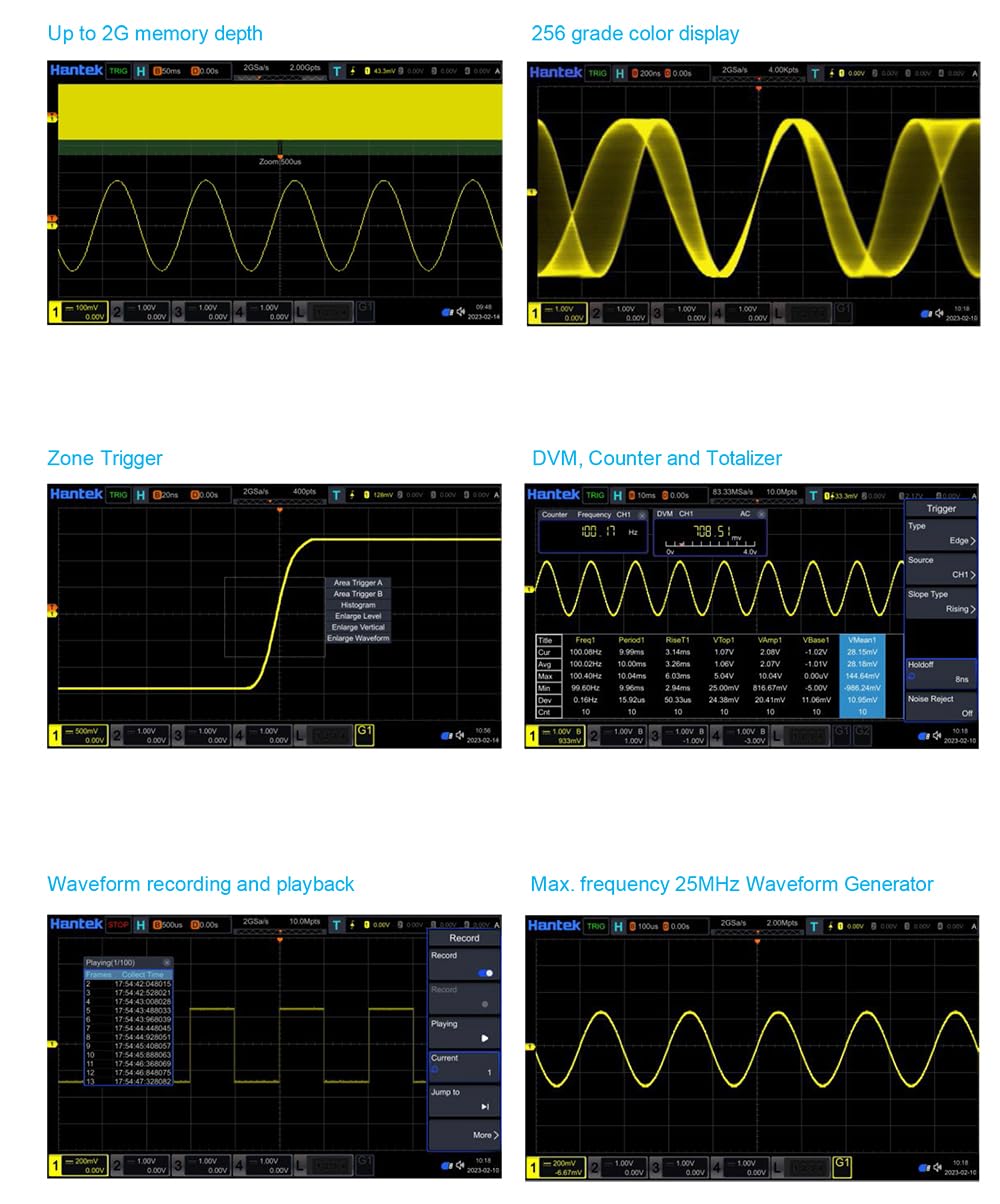
Figure 5.2.1: Zone Trigger Interface. This image illustrates the Zone Trigger feature, where specific areas on the oscilloscope display can be defined to trigger waveform acquisition based on whether the signal enters or avoids these zones.
5.3 Measurements
The oscilloscope provides both manual cursor measurements and a wide range of automatic measurements.
- Cursors: Two pairs of XY cursors for manual voltage (ΔY) and time (ΔX) measurements. Track mode allows cursors to follow waveform points.
- Auto Measurements: Select up to 7 measurements simultaneously from categories including Time (Frequency, Period, Rise Time, Fall Time, Width, Duty Cycle), Voltage (Peak-to-peak, Average, Max, Min, RMS), and Other (Phase, Area).
5.4 Waveform Generator
The built-in 25MHz waveform generator can produce various standard and arbitrary waveforms.
- Waveform Types: Sine, Square, Ramp, Noise, Pulse, DC, Sine Cardinal, Exponential Fall, Half Sine, Lorentz, Dual Tone, Gauss, ECG, Arbitrary.
- Frequency and Amplitude: Adjustable parameters for each waveform type.

Figure 5.4.1: Waveform Generator Output. This image displays the oscilloscope screen showing a generated sine wave, demonstrating the functionality of the built-in 25MHz waveform generator.
5.5 Digital Voltmeter (DVM) & Counter
The DPO7104U integrates a 5-digit DVM and a 6-digit frequency counter with totalizer function.
- DVM Functions: AC RMS, AC+DC RMS, DC voltage measurements.
- Counter: Measures frequency and counts events.

Figure 5.5.1: DVM and Counter Display. This image shows the oscilloscope display with the Digital Voltmeter (DVM) and Frequency Counter readings, providing precise numerical measurements alongside the waveform.
5.6 Waveform Recording & Playback
Capture and replay long waveform sequences for detailed analysis.
- Recording: Record waveforms into the internal memory.
- Playback: Review recorded waveforms using navigation controls.

Figure 5.6.1: Waveform Recording and Playback. This image illustrates the interface for recording and playing back waveforms, allowing users to capture and review transient events or long-duration signals.
5.7 Spectrum Analyzer (FFT)
The DPO7104U includes a Fast Fourier Transform (FFT) function for spectrum analysis, allowing you to view the frequency components of your signal.
6. Specifications
The following table details the technical specifications for the Hantek DPO7104U Digital Storage Oscilloscope.

Figure 6.1.1: Detailed Specifications. This image provides a comprehensive table of technical specifications for the Hantek DPO7000U series, including bandwidth, sample rate, memory depth, display characteristics, and various vertical, horizontal, acquisition, and trigger parameters.
| Category | Parameter | Specification (DPO7104U) |
|---|---|---|
| Overview | Analog Bandwidth (-3 dB) | 100MHz |
| Rise Time at BNC (typical) | ≤3.5ns | |
| Analog Channel | 4 | |
| Max. Sample Rate | 2GSa/s (single channel), 1GSa/s (half or all channels) | |
| Max. Memory Depth | 2Gpts (single channel), 1Gpts (half channels), 500Mpts (three or all channels) | |
| Display Type | 10.1 inch capacitive multitouch screen | |
| Display Resolution | 1024 horizontal by 600 vertical pixels | |
| Waveform Update Rate (Typical) | Up to 500,000 wfms/s (at 25ns, single channel, auto memory depth) | |
| External Trigger | 1 | |
| Waveform Color Persistence | Standard | |
| Counter | 6-digit frequency counter + totalizer | |
| Integrated Digital Voltmeter | Standard | |
| Waveform Recorder | Standard | |
| Built-in Waveform Generator | 1CH, 25MHz | |
| Connectivity | USB Host, USB Device (Type C), LAN | |
| Vertical System | Input Coupling | AC, DC, GND |
| Input Impedance/Capacitance | 1MΩ±1%, 50Ω±1% / 19pF±3pF | |
| Probe Attenuation Coefficient | 0.01X to 50000X | |
| Vertical Resolution | 8-bit | |
| Max. Input Voltage | CAT I 300Vrms, 400Vpk (1MΩ); 5Vrms (50Ω) | |
| Input Sensitivity Range | 500μV/div to 10V/div (1MΩ); 500μV/div to 1V/div (50Ω) | |
| Bandwidth Limits | 20MHz, 100MHz, 200MHz, 350MHz (selectable) | |
| DC Gain Accuracy | <200 mV/div (±0.1div ± 2mV ± 1.5% offset); >200 mV/div (±0.1div ± 2mV ± 1.0% offset) | |
| Channel to Channel Isolation | 40dB from DC to max specified bandwidth | |
| ESD Tolerance | ±8 KV (at input BNC) | |
| Horizontal System | Time Base Range | 500ps/div to 1ks/div |
| Time Accuracy | ±1ppm ±1ppm per year | |
| Time Base Delay | Pre-Trigger, Post-Trigger | |
| Delta Time Accuracy (using cursors) | ± (1 sample interval) ± (2ppm × reading) ± 50ps | |
| Channel to Channel Deskew Time | ± 100 ns | |
| Modes | YT, XY, SCAN, ROLL | |
| Dynamic Range | ±5 div (8 bit) | |
| Acquisition | Max. Sample Rate | 2GSa/s (half channels), 1GSa/s (all channels) |
| Max. Record Length | 1Gpts (half channels), 500Mpts (three or all channels) | |
| Acquisition Mode | Normal, Peak Detect, Average (2 to 65536) | |
| High Resolution | Max. 12 bits | |
| Waveform Capture Rate | Up to 500,000 wfms/s | |
| Trigger System | Trigger Source | CH1, CH2, CH3, CH4, EXT |
| Trigger Modes | Normal, Auto, Single, Force | |
| Trigger Holdoff Range | 8ns to 10s | |
| Trigger Bandwidth | Analog bandwidth | |
| Trigger Sensitivity | < 10 mV/div: greater of 1 div or 5mV; ≥ 10 mV/div: 0.5 div | |
| Trigger Level Range | ± 4 div from center screen | |
| Zone Trigger (HW zone qualifier) | User-defined zones, 'must intersect' or 'must not intersect', up to two zones | |
| Trigger Types | Edge, Pulse, Video, Slope, Overtime, Window, Runt, OverAmp, Pattern, Delay, Setup/Hold | |
| Measurements | Number of Cursors | 2 pairs of XY cursors |
| Manual Mode | ΔY, ΔX, 1/ΔX (Hz) | |
| Track Mode | Fix Y axis to track X, Fix X axis to track Y | |
| Auto Measurements | 51 types (Time, Voltage, Other) | |
| Waveform Math | Arithmetic | A+B, A-B, A*B, A/B, FFT, A&&B, A||B, A^B, !A, Intg, Diff, Sqrt, Lg, Ln, Exp, Abs, LowPass, HighPass, BandPass, BandStop, AX+B, Expression |
| Window Types | Hanning, Hamming, Flattop, Rectangular, Triangle, Blackman | |
| FFT | Peak search: Max 15 peaks | |
| DVM | Functions | AC RMS, AC+DC RMS, DC |
| Data Source | CH1, CH2, CH3, CH4 | |
| Resolution | 3 digits |
7. Maintenance
7.1 Cleaning
To clean the instrument, use a soft cloth dampened with a mild detergent and water. Do not use abrasive cleaners or solvents that may damage the instrument's casing or display. Ensure the instrument is powered off and disconnected from all power sources before cleaning.
7.2 Storage
When not in use, store the oscilloscope in a dry, dust-free environment away from direct sunlight and extreme temperatures. Use the original packaging or a suitable carrying case for protection during transport.
8. Troubleshooting
This section provides solutions to common issues you might encounter. If the problem persists, contact customer support.
- No Power:
- Check if the power cable is securely connected to both the oscilloscope and the power outlet.
- Verify that the power outlet is functional.
- Check the fuse in the power input. Replace if necessary with the correct type and rating.
- No Signal Displayed:
- Ensure the input probe is correctly connected to the channel and the circuit under test.
- Verify that the channel is enabled (press the corresponding CH button).
- Adjust the vertical scale (Volts/Div) and horizontal time base (Time/Div) to appropriate settings.
- Check the trigger settings. Try setting the trigger mode to 'Auto' to see if a waveform appears.
- Unstable Waveform:
- Adjust the trigger level to a stable point on the waveform.
- Ensure the trigger source is set to the correct channel.
- Select an appropriate trigger type for the signal being measured (e.g., Edge trigger for repetitive signals).
9. Warranty and Support
Hantek products are designed for reliability and performance. For warranty information, please refer to the warranty card included with your product or visit the official Hantek website. For technical support, service, or inquiries, please contact your local distributor or Hantek customer service through their official channels.
Please have your product model number (DPO7104U) and serial number ready when contacting support.


