
1. Introduction
The Hantek DPO7104U-100MHz is a versatile 5-in-1 instrument designed for comprehensive electronic testing and analysis. It integrates a 4-channel digital storage oscilloscope, a 1-channel waveform generator, a spectrum analyzer, a digital voltmeter (DVM), and a frequency counter into a single, compact device. This manual provides essential information for setting up, operating, and maintaining your instrument to ensure optimal performance and longevity.
2. Safety Information
Please read and understand all safety instructions before operating the device. Failure to follow these instructions may result in electric shock, fire, or damage to the instrument. Keep the device away from moisture and extreme temperatures. Ensure proper ventilation during operation. Only use accessories and power cables provided or approved by Hantek.
3. Package Contents
Verify that all items listed below are present in your package:
- 1 x Hantek DPO7104U-100MHz Digital Storage Oscilloscope
- 4 x Oscilloscope Probes
- 1 x USB Cable
- 1 x Power Cable
- 1 x Software CD (for PC connectivity)

Image: The Hantek DPO7104U-100MHz oscilloscope shown with its standard accessories, including four probes, a USB cable, and a power cable.
4. Product Overview
The DPO7104U-100MHz is a high-performance digital storage oscilloscope featuring a 10.1-inch capacitive touchscreen display with 256-level intensity grading and color persistence for clear waveform visualization. It offers 4 analog channels with 100MHz bandwidth and a 2GSa/s sample rate, along with a maximum 2Gpts memory depth. The device also includes a built-in 25MHz waveform generator, spectrum analyzer, 5-digit DVM, and 6-digit frequency counter.

Image: Front view of the Hantek DPO7104U-100MHz oscilloscope, showcasing its large 10.1-inch LCD screen and control panel with various buttons and knobs.

Image: Side view of the Hantek DPO7104U-100MHz oscilloscope, highlighting its compact design and ventilation grilles.

Image: Rear view of the Hantek DPO7104U-100MHz oscilloscope, showing various connectivity ports including LAN, USB, and external trigger inputs/outputs.
5. Setup
- Power Connection: Connect the provided power cable to the instrument's power input and then to a suitable AC power outlet.
- Initial Power On: Press the power button located on the front panel. The device will perform a self-test and boot up.
- Probe Connection: Connect the oscilloscope probes to the desired input channels (CH1-CH4) on the front panel. Ensure the probes are properly calibrated before use.
- External Connections: For PC connectivity, use the USB Host or USB Device (Type C) ports. For network control, connect an Ethernet cable to the LAN port.
Video: This video demonstrates the unboxing, quick startup, and control panel overview of a similar Hantek DSO2000 series oscilloscope, providing a visual guide to initial setup and basic interface navigation.
6. Operating Instructions
6.1. Oscilloscope Functions
- Channel Selection: Use the dedicated channel buttons (CH1-CH4) to enable or disable channels and access their individual settings.
- Vertical Controls: Adjust the vertical scale (Volts/Div) and position using the corresponding knobs for each channel. The minimum vertical range is 500µV/div.
- Horizontal Controls: Adjust the time base (Sec/Div) and horizontal position using the dedicated knobs.
- Trigger System: Configure trigger settings (edge, pulse, video, slope, overtime, window, etc.) to stabilize waveforms. The device supports various trigger modes.
- Acquisition Mode: Select between Normal, Peak Detect, and Average acquisition modes.
- Memory Depth: Utilize the deep memory (up to 2Gpts) to capture long waveform sequences with high resolution.
- Waveform Capture Rate: Benefit from a high waveform capture rate of up to 500,000 wfms/s for observing transient events.
6.2. Waveform Generator
The built-in 1-channel, 25MHz waveform generator can output various standard and arbitrary waveforms, including sine, square, ramp, noise, pulse, DC, sine cardinal, exponential fall, haversine, lorentz, dual tone, gause, and ECG. Connect the generator output to an input channel to view the generated waveform.
6.3. Spectrum Analyzer
The integrated spectrum analyzer allows for frequency domain analysis of signals, providing insights into harmonic content and signal purity. Access this function through the utility menu.
6.4. Digital Voltmeter (DVM) & Frequency Counter
The DPO7104U-100MHz includes a 5-digit digital voltmeter and a 6-digit frequency counter with totalizer functionality for precise measurement of voltage and frequency parameters.
6.5. Automatic Measurements & Math Functions
The instrument offers 51 auto measurements and a statistics display for quick analysis of waveform parameters. It also features 20 basic and advanced math functions, including FFT (Fast Fourier Transform) for spectral analysis. Utilize the zone trigger function and reference waveforms for advanced analysis.
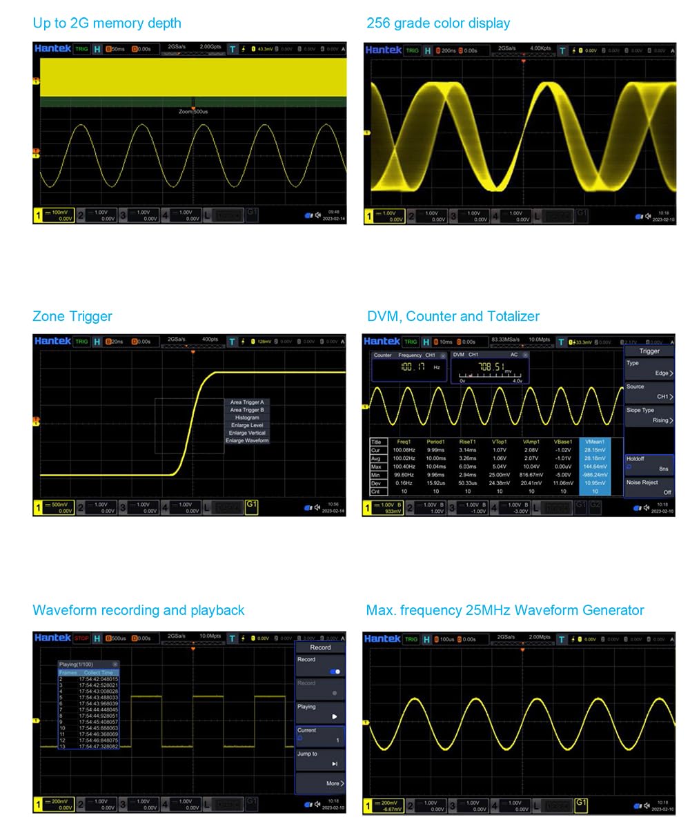
Image: The oscilloscope display showing various functions simultaneously, including waveform recording, 256-grade color display, zone trigger, DVM, counter, and the maximum 25MHz waveform generator output.
6.6. Connectivity and Remote Control
The device supports standard USB Host, USB Device (Type C), and LAN ports for flexible connectivity. It also supports SCPI remote command control for automated testing and integration into larger systems.
7. Maintenance
- Cleaning: Use a soft, dry cloth to clean the exterior of the instrument. For the screen, use a soft, lint-free cloth specifically designed for electronic displays. Do not use abrasive cleaners or solvents.
- Storage: Store the instrument in a dry, dust-free environment away from direct sunlight and extreme temperatures.
- Calibration: Regular calibration is recommended to maintain measurement accuracy. Refer to the full service manual for calibration procedures or contact Hantek support.
8. Troubleshooting
- No Power: Ensure the power cable is securely connected and the power outlet is functional. Check the power switch.
- No Waveform Display: Verify that probes are correctly connected to the input channels and the signal source. Check trigger settings and vertical/horizontal scales.
- Incorrect Measurements: Ensure probes are properly calibrated and the measurement settings are appropriate for the signal being analyzed.
- Device Unresponsive: Try restarting the instrument. If the issue persists, contact technical support.
9. Specifications
Detailed technical specifications for the Hantek DPO7104U-100MHz are provided below:

Image: Page 1 of the detailed specifications for the Hantek DPO7104U-100MHz oscilloscope, covering overview, analog bandwidth, channels, sample rate, memory depth, display type, and more.

Image: Page 2 of the detailed specifications for the Hantek DPO7104U-100MHz oscilloscope, detailing vertical, horizontal, and acquisition parameters.
9.1. Overview
- Analog Bandwidth (-3 dB): 100MHz
- Rise Time at BNC (typical): ≤3.5ns
- Analog Channel: 4
- Max. Sample Rate: 2GSa/s for single channels, 1GSa/s for half or all channels
- Max. Memory Depth: 2Gpts for single channel, 500Mpts for three or all channels
- Display Type: 10.1 inch capacitive multitouch screen
- Display Resolution: 1024 horizontal by 600 vertical pixels
- Waveform Update Rate (Typical): Up to 500,000 wfms/s (at 25ns, single channel, auto memory depth)
- External Trigger: 1
- Waveform Color Persistence: Standard
- Counter: 6-digit frequency counter + totalizer
- Integrated Digital Voltmeter: Standard
- Waveform Recorder: Standard
- Search and Navigation: Standard (supporting table display)
- Hardware Mask Test: Standard
- Built-in Waveform Generator: 1CH, 25MHz
- FFT: Standard
- MATH: Displays 4 functions simultaneously
- Connectivity: USB Host, USB Device (Type C), LAN
9.2. Oscilloscope - Vertical
- Input Coupling: AC, DC, GND
- Input Impedance/Capacitance: 1MΩ±1%, 50Ω±1% / 19pF±3pF
- Probe Attenuation Coefficient: 0.01X, 0.02X, 0.05X, 0.1X, 0.2X, 0.5X, 1X, 2X, 5X, 10X, 20X, 50X, 100X, 200X, 500X, 1000X, 2000X, 5000X, 10000X, 20000X, and 50000X
- Vertical Resolution: 8-bit
- Max. Input Voltage: CAT I 300Vrms, 400Vpk, transient overvoltage 1600Vpk in 1MΩ, 5Vrms in 50Ω
- Input Sensitivity Range: 500µV/div to 10V/div in 1MΩ, 500µV/div to 1V/div in 50Ω
- Offset Range: ±1V (500µV/div to 50mV/div), ±10V (100mV/div to 500mV/div), ±100V (1V/div to 10V/div)
- Bandwidth Limits: 20MHz, 100MHz (selectable for each channel)
- Dynamic Range: ±5 div (8 bit)
- Channel to Channel Isolation: 40dB from DC to the maximum specified bandwidth
- DC Gain Accuracy: <200 mV/div (±0.1div ± 2mV ± 1.5% offset setting), >200 mV/div (±0.1div ± 2mV ± 1.0% offset setting)
- ESD Tolerance: ±8 kV (at input BNC)
9.3. Oscilloscope - Horizontal
- Time Base Range: 500ps/div to 1ks/div
- Time Accuracy: ±1ppm ±1ppm per year
- Time Base Delay: Pre-Trigger, Post-Trigger
- Time Range: Greater of 1/2 screen width, 1s or 100 div (take the bigger value)
- Delta Time Accuracy (using cursors): ± (1 sample interval) ± (2ppm × reading) ± 50ps
- Channel to Channel Deskew Time: ± 100 ns
- Modes: YT (X1 = channel 1, Y1 = channel 2), XY (Displays the volts vs volts display), SCAN (Available at the timebase settings of 100 ms/div or slower), ROLL (Available at the timebase settings of 100 ms/div or slower)
9.4. Oscilloscope - Acquisition
- Max. Sample Rate: 2GSa/s for half channels, 1GSa/s for all channels
- Max. Record Length: 2Gpts for single channel, 500Mpts for three or all channels
- Acquisition Mode: Normal (Default), Peak Detect (Capture glitches as narrow as 1ns at all time base settings), Average (Selectable from 2, 4, 8, 16, ... to 65536), High Resolution (Max. 12 bits)
10. Warranty and Support
Hantek provides a standard warranty for this product against defects in materials and workmanship. For detailed warranty terms, technical support, or service inquiries, please refer to the warranty card included in your package or visit the official Hantek website. Please have your model number (DPO7104U-100MHz) and serial number ready when contacting support.