1. Introduction
This manual provides essential information for the safe and effective operation, setup, and maintenance of your ARCCAPTAIN iControl MIG205 Pro Welder and accompanying Large Viewing Screen Welding Helmet. Please read this manual thoroughly before using the equipment to ensure proper function and safety.
1.1 Safety Information
Welding can be dangerous. Always follow safety precautions to prevent injury or damage. Wear appropriate personal protective equipment (PPE), including the welding helmet, gloves, and protective clothing. Ensure adequate ventilation in the work area. Disconnect power before performing any maintenance or adjustments. Refer to local safety regulations and standards for welding operations.
2. Package Contents
Verify that all items listed below are present in your package:
- ARCCAPTAIN iControl MIG205 Pro Welder
- ARCCAPTAIN Large Viewing Screen Welding Helmet
- MIG Torch
- Ground Clamp
- Electrode Holder (for MMA Stick welding)
- Gas Hose
- Contact Tips
- Drive Rollers
- User Manual
- Power Cord
3. Product Overview
3.1 ARCCAPTAIN iControl MIG205 Pro Welder
The ARCCAPTAIN iControl MIG205 Pro is a versatile 6-in-1 welding machine designed for various welding applications. It supports Gas MIG, Gasless MIG (Flux Core), MMA Stick, Lift TIG, Spot Welding, and Spool Gun Aluminum Welding modes. The welder features a 205A output, 120V/240V dual voltage input, and an advanced 40W wire feeding mechanism.
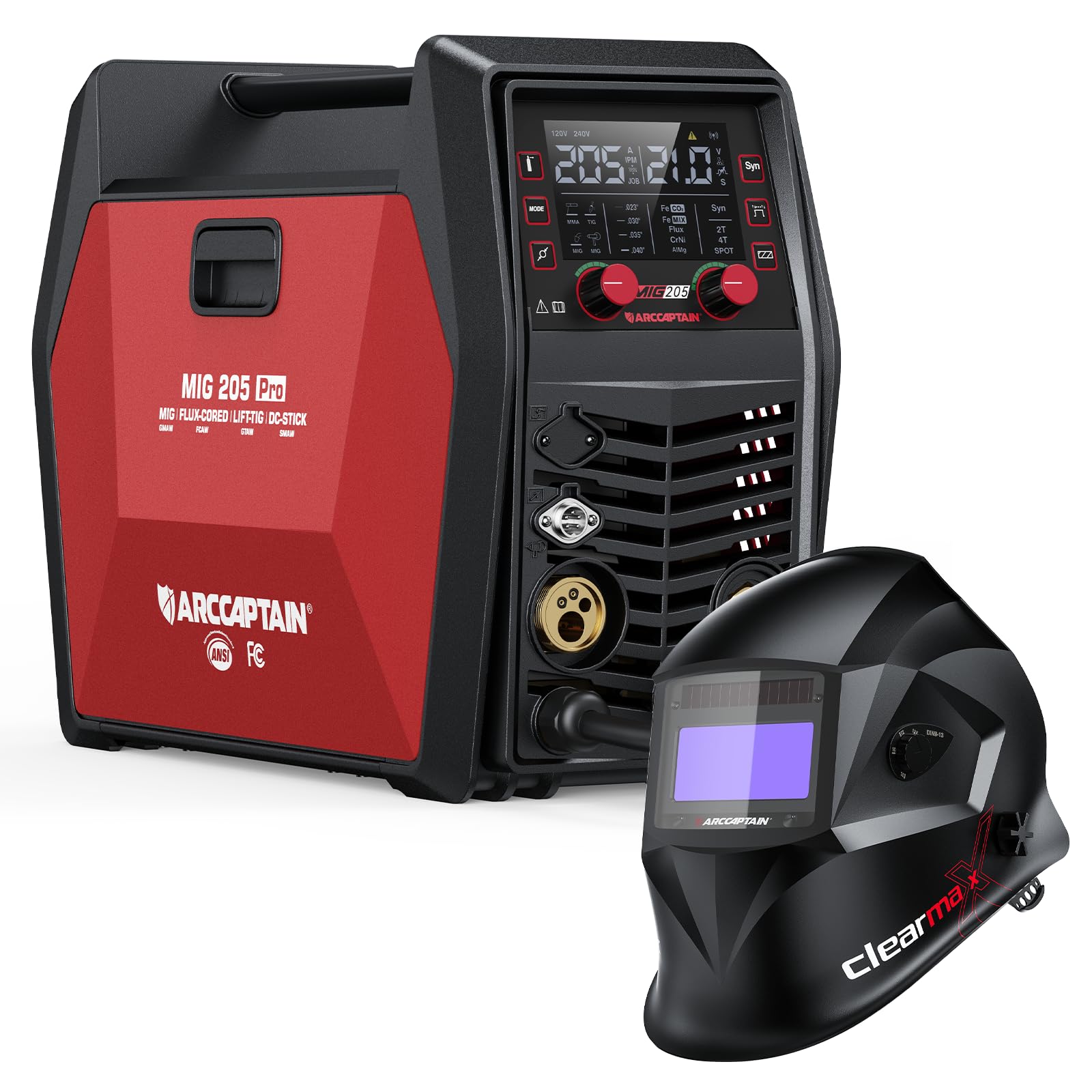
Figure 1: ARCCAPTAIN iControl MIG205 Pro Welder and included accessories.

Figure 2: Overview of the six welding modes supported by the MIG205 Pro welder.
The welder incorporates an exclusive human-computer interaction LED screen for clear data display and easy parameter adjustments. It also features upgraded MCU technology, dual smart fans for efficient cooling, and a powerful 40W motor for wire feeding up to 640 inches per minute (IPM).

Figure 3: Internal technology upgrades including MCU, cooling fans, and wire feed motor.
Precision control features include adjustable inductance (-10 to +10), burn-back time (150-250ms), and spot time (0.5-5s) for optimal weld quality.

Figure 4: Precision settings for welding parameters.
3.2 ARCCAPTAIN Large Viewing Screen Welding Helmet
The included ARCCAPTAIN welding helmet features a large viewing screen with True Color technology, providing a clear and natural view of the weld puddle. It boasts an optical class of 1/1/1/1, ensuring high clarity and minimal distortion. The helmet is constructed from durable PA material and offers a fast darkening speed of 1/25000s with four premium sensors.

Figure 5: ARCCAPTAIN Large Viewing Screen Welding Helmet.

Figure 6: True Color technology comparison for welding helmet screens.

Figure 7: Key features of the ARCCAPTAIN welding helmet.
4. Setup
4.1 Welder Setup
- Power Connection: Connect the welder to a suitable 120V or 240V power outlet. Ensure the power source matches the welder's requirements.
- Ground Clamp: Attach the ground clamp securely to the workpiece or a clean, bare metal surface connected to the workpiece.
- MIG Torch: Connect the MIG torch to the appropriate connector on the front panel of the welder.
- Wire Loading:
- Open the wire feeder compartment.
- Install the correct drive roller for your wire type and size.
- Load the welding wire onto the spool holder, ensuring it unwinds smoothly.
- Feed the wire through the guide tube and into the drive roller mechanism.
- Close the drive roller tension arm and adjust tension as needed.
- With the torch pointed away from yourself and others, press the trigger to feed the wire through the torch liner until it exits the contact tip.
- Gas Connection (for Gas MIG):
- Connect the gas hose from your gas cylinder regulator to the gas inlet on the rear of the welder.
- Ensure all connections are tight to prevent leaks.
- Open the gas cylinder valve and adjust the flow rate on the regulator to the recommended setting (typically 15-25 CFH for MIG).
4.2 Welding Helmet Setup
- Headgear Adjustment: Adjust the headgear straps for a comfortable and secure fit. Ensure the helmet sits evenly on your head and the viewing area is aligned with your eyes.
- Shade and Sensitivity Adjustment: Use the external knobs to set the desired shade level (DIN4/9-13) and sensitivity for the auto-darkening filter. Test the auto-darkening function before welding by briefly exposing the sensors to a bright light source.
5. Operating Instructions
5.1 Selecting Welding Mode
Turn on the welder. Use the mode selection button on the control panel to cycle through the available welding processes: Gas MIG, Gasless MIG, MMA Stick, Lift TIG, Spot Welding. The selected mode will be displayed on the LED screen.
5.2 Adjusting Parameters
Once a mode is selected, use the control knobs to adjust welding parameters such as voltage, wire feed speed, amperage (for Stick/TIG), inductance, burn-back time, and spot time. Refer to the welding chart provided with your wire for recommended settings based on material type and thickness.

Figure 8: Welder control via smartphone application.
The ARCCAPTAIN iControl MIG205 Pro also supports app control for customizable settings and quick access to saved preferences. Download the official ARCCAPTAIN app to utilize this feature.
5.3 Welding Techniques
- MIG Welding: Maintain a consistent stick-out and travel speed. Use a push or pull technique depending on the desired bead profile and penetration.
- MMA Stick Welding: Select the appropriate electrode for your material. Maintain a short arc length and consistent travel speed.
- Lift TIG Welding: Requires a separate Lift TIG torch (not included). Initiate the arc by touching the tungsten to the workpiece and then lifting slightly. Maintain a consistent arc length and feed filler rod manually.
- Spot Welding: Position the torch over the desired spot. The welder will automatically control the weld time based on settings.
6. Maintenance
6.1 Welder Maintenance
- Regular Cleaning: Keep the welder clean and free from dust and metal particles. Use compressed air to blow out internal components periodically.
- Wire Feeder: Inspect the drive rollers for wear and cleanliness. Ensure the wire liner is free of kinks and blockages.
- MIG Torch: Regularly clean or replace the contact tip, nozzle, and diffuser. Check for spatter buildup.
- Cables: Inspect all cables for damage, cuts, or frayed insulation. Replace damaged cables immediately.
6.2 Welding Helmet Maintenance
- Lens Cleaning: Clean the outer and inner protective lenses with a soft cloth and mild soap solution. Do not use abrasive cleaners.
- Sensor Inspection: Keep the auto-darkening sensors clean and unobstructed.
- Battery Check: If your helmet uses replaceable batteries, check and replace them as needed.
- Storage: Store the helmet in a dry, clean place away from direct sunlight and extreme temperatures.
7. Troubleshooting
| Problem | Possible Cause | Solution |
|---|---|---|
| No arc/Poor arc starting |
|
|
| Wire feeding issues (stuttering, no feed) |
|
|
| Welding helmet not darkening |
|
|
For issues not listed here, please contact ARCCAPTAIN customer support.
8. Specifications
8.1 ARCCAPTAIN iControl MIG205 Pro Welder
- Model: MIG205 Pro
- Welding Modes: Gas MIG, Gasless MIG, MMA Stick, Lift TIG, Spot Welding, Spool Gun Aluminum Welding
- Output Current: 205A (Maximum)
- Input Voltage: 120V/240V Dual Voltage
- Wire Feed Speed: Up to 640 IPM (inches per minute)
- Wire Feeder Motor: 40W
- Cooling System: Dual Smart Fans
- Control Interface: Large LED Display, App Control
- Precision Settings: Inductance (-10 to +10), Burn-back time (150-250ms), Spot time (0.5-5s)
8.2 ARCCAPTAIN Large Viewing Screen Welding Helmet
- Optical Class: 1/1/1/1
- Viewing Screen: Large, True Color HD LCD Dimming Screen
- Shade Range: DIN4/9-13
- Darkening Speed: 1/25000s
- Sensors: 4 Premium Sensors
- Material: PA Durable Material
9. Warranty and Support
ARCCAPTAIN products are designed for quality and reliability. For warranty information, product support, or to purchase replacement parts, please refer to the warranty card included with your product or visit the official ARCCAPTAIN website. You may also contact ARCCAPTAIN customer service directly for assistance.
ARCCAPTAIN Customer Service: Visit ARCCAPTAIN Store on Amazon