1. Introduction
This manual provides detailed instructions for the safe and efficient operation of your PowMr 10000W Split-Phase Solar Inverter, Model POW-SunSmart 10KP. This device is a multifunctional solar energy storage inverter designed to integrate solar energy storage, utility charging, and AC sine wave output. It features dual MPPT controllers and supports parallel operation for expanded capacity.

Figure 1: Front view of the PowMr 10000W Split-Phase Solar Inverter.
2. Safety Information
Please read all instructions and warnings carefully before installation and operation. Failure to follow these instructions may result in electric shock, fire, or severe injury. Keep this manual for future reference.
- Installation must be performed by qualified personnel.
- Ensure all wiring complies with local and national electrical codes.
- Do not connect the positive or negative terminal of the solar panel directly to the ground.
- Verify correct polarity for all battery and PV connections.
- Do not attempt to disassemble or repair the inverter yourself. Contact qualified service personnel.
- Ensure adequate ventilation around the inverter to prevent overheating.
- The inverter is equipped with comprehensive protection features including short circuit, over-current, over-under voltage, overload, backfill, and over-temperature protection.

Figure 2: The inverter includes multiple protection mechanisms for safe operation, such as short circuit, over-current, over-voltage, under-voltage, overload, backfill, and over-temperature protection.
3. Product Overview
3.1 Key Features
- Output: Split-phase and single-phase pure sine wave output (120V/240V).
- Capacity: 10000W continuous power, 20000W surge power.
- MPPT Controller: Built-in dual 200A MPPT controllers with 99.9% efficiency.
- Parallel Operation: Supports up to 6 units in parallel for capacity expansion up to 60kW.
- Battery Compatibility: Compatible with AGM, Gel, Lead-acid, Lithium-ion, and LiFePO4 batteries. Supports batteryless operation.
- Charging Modes: Four selectable charging modes: Solar Only, Mains Priority, Solar Priority, and Mixed Mains/PV charging.
- Output Modes: Two output modes: Utility Bypass and Inverter Output, with uninterrupted power supply function.
- Communication: Supports CAN, USB, and RS485 communication.

Figure 3: Overview of the 10KW Split-Phase Hybrid Solar Inverter's main features, including pure sine wave output, dual MPPT, battery compatibility, and parallel operation capability.
4. What's in the Box
Upon unpacking, please verify that all items listed below are present and undamaged:
- 10000W Solar Inverter
- Parallel Communication Cable
- 2 x Battery Terminal Lugs
- 2 x M5 Screws
- Instruction Manual (this document)
Note: WiFi modules, batteries, adapters, plugs, wires, and cables are not included and must be purchased separately if required.
5. Setup and Installation
Proper installation is critical for the safe and efficient operation of the inverter. Ensure all connections are secure and follow the provided diagrams.
5.1 Site Selection
- Install the inverter in a well-ventilated area, away from direct sunlight, heat sources, and moisture.
- Ensure sufficient clearance around the inverter for proper airflow.
- Mount the inverter on a non-flammable surface.
5.2 Wiring Connections
The inverter supports both split-phase and single-phase configurations. The PV input is compatible with single crystalline and polycrystalline PV modules. Do not connect the positive or negative terminal of the solar panel to the ground.

Figure 4: Detailed split-phase connection diagram illustrating PV input, mains/generator input, AC output, and battery connections. This diagram shows how to connect the inverter for 120V/240V output. For single-phase 120V output, only one live wire (L1 or L2) needs to be connected to the input and output terminals.
5.2.1 PV Input
- Number of MPPT Trackers: 2
- Max. PV Array Power: 11000W (5500W per tracker)
- Max. Input Current: 22A per tracker
- Starting Voltage: > 150V
- Max. Voltage of Open Circuit: 500V DC
- MPP Voltage Range: 125V-425V DC
- PV Cable: 10-12 AWG
5.2.2 Mains / Generator Input
- Input Voltage Range: 90-140Vac per phase
- Maximum AC Input Current: 120A
- Frequency Range: 50/60Hz
- AC Input Power: 10000W
- AC Cable: 8-6 AWG
5.2.3 AC Output
- Rated Output Power: 10000W
- Rated Output Voltage: 120(P-N)/208(P-P)/240Vac(P-P)
- Rated AC Frequency: 50/60Hz
- AC Cable: 8-6 AWG
5.2.4 Battery Connection
- Battery Type: Li-ion/Lead-Acid / User-defined
- Nominal DC Voltage: 48V DC
- DC Voltage Range: 40-62V DC
- Maximum Charging Current: 200A
5.3 Parallel Operation
The inverter supports parallel operation of up to 6 units, allowing for a total power output of up to 60000W. This feature is suitable for expanding system capacity for various applications.
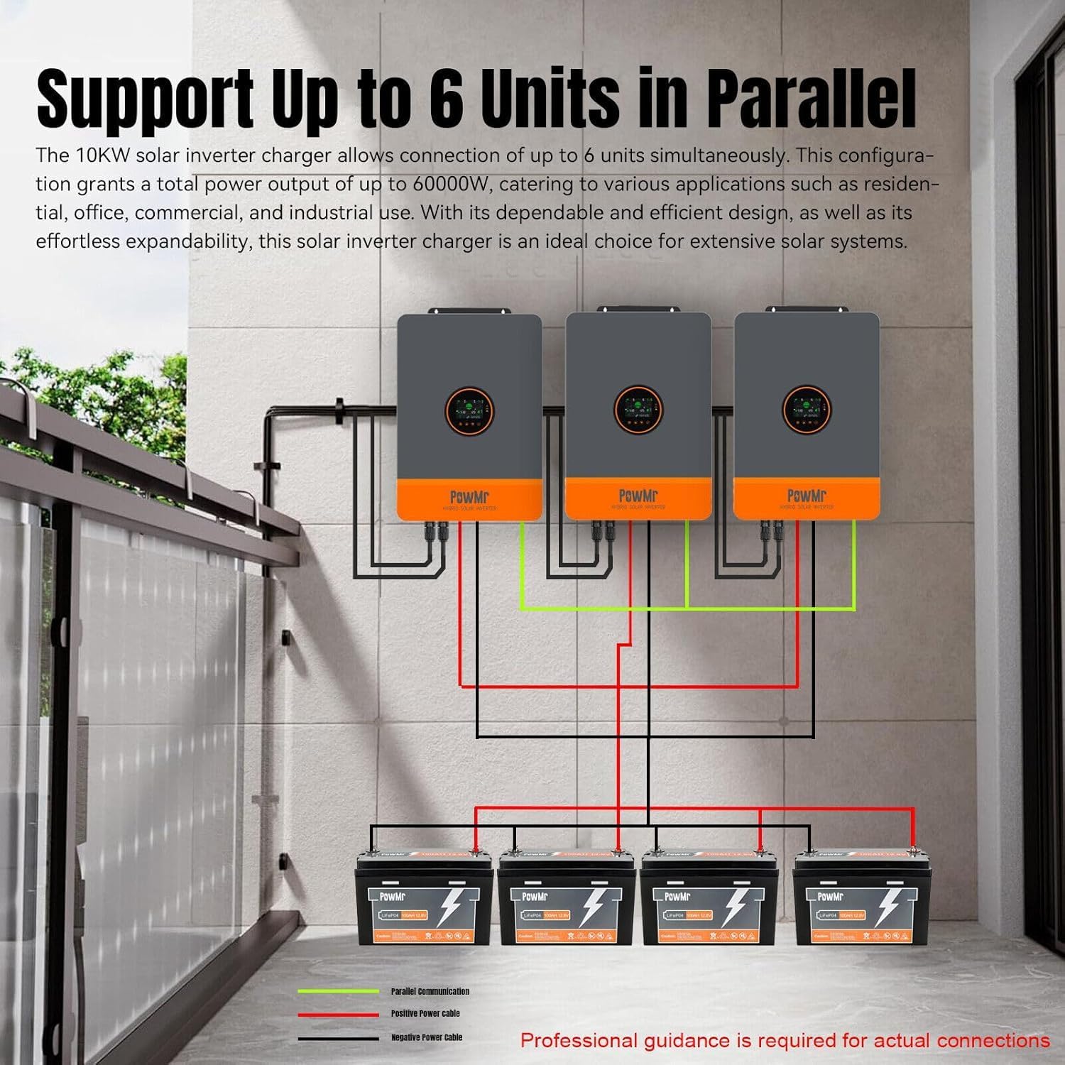
Figure 5: Illustration of connecting multiple inverters in parallel for increased power output. Professional guidance is recommended for actual connections.
6. Operating Instructions
6.1 Powering On/Off
- Power On: Ensure all connections are secure. Turn on the battery breaker first, then the AC input breaker (if applicable), and finally the PV input breaker. Press the power button on the inverter.
- Power Off: Reverse the power-on sequence. Turn off the PV input breaker, then the AC input breaker, and finally the battery breaker. Press and hold the power button to shut down the inverter.
6.2 Charging Modes
The inverter offers four selectable charging modes:
- Solar Only: Charges batteries exclusively from solar power.
- Mains Priority: Prioritizes charging from the utility grid, using solar only when grid power is unavailable.
- Solar Priority: Prioritizes charging from solar power, using the utility grid only when solar power is insufficient.
- Mixed Mains/PV Charging: Utilizes both solar and utility power for charging.
These modes can be configured via the inverter's display or the monitoring application.
6.3 Output Modes
The inverter supports two output modes:
- Utility Bypass: Loads are powered directly by the utility grid.
- Inverter Output: Loads are powered by the inverter (from batteries or solar).
The inverter provides an uninterrupted power supply function, seamlessly switching between modes.
6.4 Battery Compatibility and Activation
The inverter is compatible with various battery types, including AGM, Gel, Lead-acid, Lithium-ion, and LiFePO4. It also supports batteryless operation. For dormant Li-ion batteries, activation can be triggered by either mains power supply or photovoltaic power supply access.

Figure 6: The inverter provides 10000W AC output (20000W peak) and can simultaneously output 110Vac and 220Vac, making it compatible with a wide range of household appliances.
7. Monitoring and Control
The inverter can be monitored and controlled via the SmartESS App. A Wi-Fi/GPRS data acquisition module is required for this functionality and must be purchased separately.

Figure 7: The SmartESS App allows for remote monitoring and control of the inverter. The Wi-Fi/GPRS module (Q2721100111238) is optional and sold separately.
Download the SmartESS App from the App Store or Google Play. Once the Wi-Fi module is installed and configured, you can view real-time system data and adjust settings remotely.
8. Maintenance
Regular maintenance ensures the longevity and optimal performance of your inverter.
- Cleaning: Keep the inverter clean and free from dust. Use a dry cloth to wipe the exterior. Do not use liquid cleaners.
- Ventilation: Ensure ventilation openings are not blocked. Periodically check for dust accumulation in cooling fins.
- Connections: Periodically inspect all electrical connections for tightness and signs of corrosion.
- Battery Check: If using lead-acid batteries, check electrolyte levels and terminal conditions as per battery manufacturer guidelines.
Warning: Disconnect all power sources (PV, AC, Battery) before performing any maintenance.
9. Troubleshooting
This section provides guidance for common issues. For problems not listed here or if issues persist, contact customer support.
| Problem | Possible Cause | Solution |
|---|---|---|
| Inverter not powering on | No battery connection; Battery voltage too low; Power button not pressed correctly. | Check battery connections; Charge battery; Press and hold power button. |
| No AC output | Overload; Short circuit; Inverter fault; AC output breaker tripped. | Reduce load; Check for short circuits; Reset inverter; Check AC breaker. |
| No solar charging | PV input voltage too low; PV connections incorrect; MPPT fault. | Check PV array for shading or damage; Verify PV wiring; Contact support. |
| Error code displayed | Specific system fault. | Refer to the inverter's display for the specific error code and consult the full manual or contact customer support for detailed resolution steps. |
10. Technical Specifications
| Feature | Specification |
|---|---|
| Model Number | POW-SunSmart 10KP |
| Rated Output Power | 10000W (Continuous) |
| Surge Power | 20000W |
| Rated Output Voltage | 120/240Vac (Split-phase/Single-phase) |
| Switch Time | 10ms |
| Max. PV Input Power | 11KW (5500W * 2) |
| Max. PV Input Voltage | 500Vdc |
| Max. PV Input Current | 22A |
| PV Starting Voltage | > 150V |
| PV Wire Gauge | 10AWG |
| Battery Nominal DC Voltage | 48Vdc |
| Max. Battery Charging Current | 200A |
| Communication Interfaces | CAN, USB, RS485 |
| Dimensions (Package) | 25.2 x 18.6 x 6 inches |
| Item Weight | 59.5 pounds |
11. Warranty and Support
For warranty information and technical support, please refer to the documentation provided with your purchase or contact the manufacturer directly. Ensure you have your product model number (POW-SunSmart 10KP) and serial number ready when contacting support.
Manufacturer: Temank


