Important Safety Information
Please read and understand all safety warnings and operating instructions before using this instrument. Failure to follow these instructions may result in electric shock, fire, or serious injury.
- This clamp meter is designed to meet CAT III 600V safety standards. Always adhere to these ratings.
- Do not attempt to measure voltages or currents exceeding the specified maximum limits.
- Ensure the test leads are in good condition and properly connected before any measurement.
- Always disconnect power to the circuit before making resistance, continuity, capacitance, or diode measurements.
- Use caution when working with live circuits. Avoid contact with bare wires or terminals.
- Do not operate the meter if it appears damaged or if the battery cover is not properly closed.
- Keep hands and fingers behind the probe barriers during measurements.
- When measuring AC current, clamp around only one conductor. Clamping multiple conductors will result in an inaccurate reading.
Product Overview
The Neoteck CM-3000 is a versatile 6000-count digital clamp multimeter designed for accurate and safe electrical measurements in various applications, including home, automotive, industrial, and HVAC systems. It features auto-selection, a color screen, True RMS capability, and a wide range of measurement functions.
Key Features
- Ultimate Safety & Overload Protection: Engineered to CAT III 600V safety standards with intelligent anti-burn protection.
- 800A AC Current with 26mm High-Capacity Jaw: Capable of measuring up to 800A AC current, suitable for high inrush currents.
- Smart Auto-Identification & Manual Control: Automatically detects AC/DC voltage, continuity, and resistance, with options for manual mode selection.
- Large Color Display with Analog Bar: High-contrast color screen with a fast-response analog bar and dual-line multi-content readout.
- Wide Measurement Range: Measures AC/DC Voltage (up to 600V), AC Current (up to 800A), Resistance, Continuity, Diode, Capacitance, and Frequency.
- Essential Pro Features: Non-Contact Voltage (NCV) detection, clamp head light, bright backlight, and Max/Min function.
Components
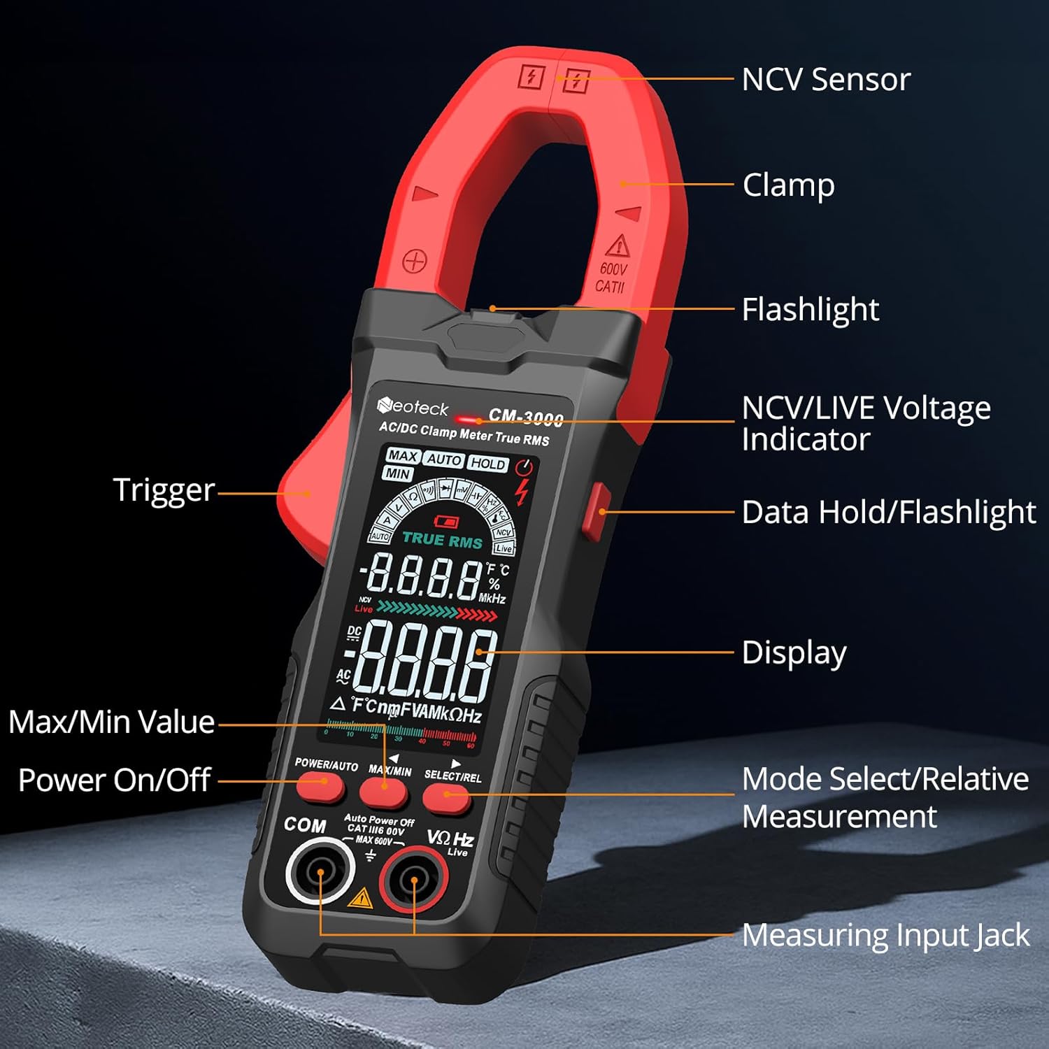
Setup
Battery Installation
- Ensure the meter is powered off.
- Locate the battery compartment on the back of the meter.
- Use a screwdriver to open the battery cover.
- Insert three AAA batteries, observing correct polarity (+/-).
- Replace the battery cover and secure it with the screw.
Connecting Test Leads
- For voltage, resistance, continuity, diode, capacitance, and frequency measurements, insert the red test lead into the VΩHz input jack and the black test lead into the COM input jack.
- Ensure connections are firm before proceeding with measurements.
Operating Instructions
Power On/Off
Press the POWER/AUTO button to turn the meter on. Press and hold the POWER/AUTO button to turn it off. The meter also features an auto-power-off function to conserve battery life.
Auto Mode vs. Manual Mode
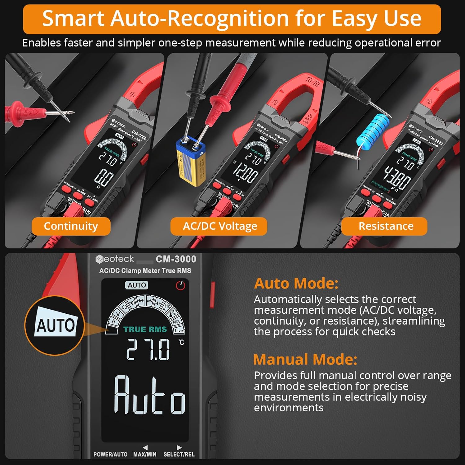
- Auto Mode: The default mode. The meter automatically selects the correct measurement function (AC/DC voltage, continuity, or resistance) when test leads are applied. This streamlines quick checks.
- Manual Mode: Press the SELECT/REL button to cycle through available measurement functions (e.g., VΩHz, Diode, Capacitance, Frequency). This provides full control for specific diagnostics.
AC Current Measurement (800A Max)

- Ensure the meter is in AC Current mode (indicated by 'A' on the display). If in Auto mode, press SELECT/REL until 'A' is shown.
- Open the clamp jaw by pressing the trigger.
- Place the jaw around a single conductor of the circuit you wish to measure.
- Close the jaw securely. The current reading will appear on the display.
- Important: For accurate readings, clamp around only one wire. Clamping multiple wires will result in an inaccurate reading.
Video 1: Demonstrates the Neoteck CM-3000 Clamp Meter in action, showcasing its features and how to perform AC current measurements. This video is provided by Neoteck US.
AC/DC Voltage Measurement (600V Max)

- Insert the red test lead into the VΩHz jack and the black test lead into the COM jack.
- Turn on the meter. In Auto mode, it will automatically detect AC or DC voltage. To manually select, press SELECT/REL until 'V' (for voltage) is displayed, then toggle between ACV and DCV if necessary.
- Connect the test probes across the circuit or component to be measured.
- Read the voltage value on the display.
Resistance Measurement
- Ensure the circuit is de-energized before measuring resistance.
- Insert test leads as for voltage.
- In Auto mode, the meter will detect resistance. To manually select, press SELECT/REL until 'Ω' (Ohms) is displayed.
- Connect the test probes across the component.
- Read the resistance value.
Continuity Test
- Ensure the circuit is de-energized.
- Insert test leads as for voltage.
- In Auto mode, the meter will detect continuity. To manually select, press SELECT/REL until the continuity symbol (a speaker icon) is displayed.
- Connect the test probes across the circuit or component.
- If continuity exists (resistance below approximately 50Ω), the buzzer will sound.
Diode Test
- Ensure the circuit is de-energized.
- Insert test leads as for voltage.
- Press SELECT/REL until the diode symbol is displayed.
- Connect the red probe to the anode and the black probe to the cathode of the diode.
- The display will show the forward voltage drop. Reverse the probes; an open circuit ('OL') indicates a good diode.
Capacitance Measurement
- Ensure the capacitor is fully discharged before measurement to prevent damage to the meter.
- Insert test leads as for voltage.
- Press SELECT/REL until the capacitance symbol ('F') is displayed.
- Connect the test probes across the capacitor terminals.
- Read the capacitance value on the display.
Frequency Measurement
- Insert test leads as for voltage.
- Press SELECT/REL until 'Hz' is displayed.
- Connect the test probes across the circuit where frequency is to be measured.
- Read the frequency value on the display.
Non-Contact Voltage (NCV) Detection
- Press the NCV/LIVE button to activate NCV mode.
- Move the NCV sensor (located at the top of the clamp jaw) close to a live conductor.
- The meter will emit an audible alarm and the NCV indicator light will flash, indicating the presence of AC voltage.
Live Wire Detection
- Press the NCV/LIVE button twice to activate Live Wire mode.
- Use the red test probe to touch the suspected live wire.
- The display will show 'LIVE' and an audible alarm will sound if a live wire is detected.
Data Hold / Max/Min Function
- Data Hold: Press the MAX/MIN button briefly to freeze the current reading on the display. Press again to release.
- Max/Min: Press and hold the MAX/MIN button to enter Max/Min recording mode. The meter will display the maximum or minimum value measured since entering this mode. Press briefly to toggle between MAX and MIN. Press and hold again to exit.
Maintenance
Cleaning
Wipe the meter with a dry, soft cloth. Do not use abrasives or solvents. Keep the clamp jaw free of dust and debris.
Battery Replacement
When the battery indicator appears on the display, replace the batteries as described in the Setup section. Remove batteries if the meter will not be used for an extended period.
Storage
Store the meter in its protective pouch in a cool, dry place, away from direct sunlight and extreme temperatures.
Troubleshooting
| Problem | Possible Cause | Solution |
|---|---|---|
| Meter does not power on. | Dead or incorrectly installed batteries. | Replace batteries, ensuring correct polarity. |
| Inaccurate AC current reading. | Clamping multiple conductors; conductor not centered. | Ensure only one conductor is within the jaw and centered. |
| 'OL' (Overload) displayed. | Measurement exceeds meter's range; open circuit. | Check if the measured value is within range. For continuity/resistance, 'OL' indicates an open circuit. |
| No continuity beep. | Resistance too high; meter not in continuity mode. | Ensure circuit is de-energized. Select continuity mode. Check for actual continuity. |
| Display is dim or flickering. | Low battery. | Replace batteries. |
Specifications
| Parameter | Value |
|---|---|
| Display | 6000 Counts, Color Screen |
| AC Current Range | 6A/60A/800A (±1.5%+5) |
| AC/DC Voltage Range | Up to 600V (AC/DC) |
| Resistance Range | 600Ω/6kΩ/60kΩ/600kΩ/6MΩ/60MΩ |
| Capacitance Range | 6nF/60nF/600nF/6uF/60uF/600uF/6mF/60mF |
| Frequency Range | 10Hz/100Hz/1kHz/10kHz/100kHz/1MHz/10MHz |
| Jaw Opening | 26mm |
| Safety Rating | CAT III 600V |
| Power Source | 3 x AAA Batteries (included) |
| Dimensions (L x W x H) | 7.28 x 2.56 x 1.26 inches |
| Item Weight | 12.3 ounces (350 Grams) |
What's in the Box
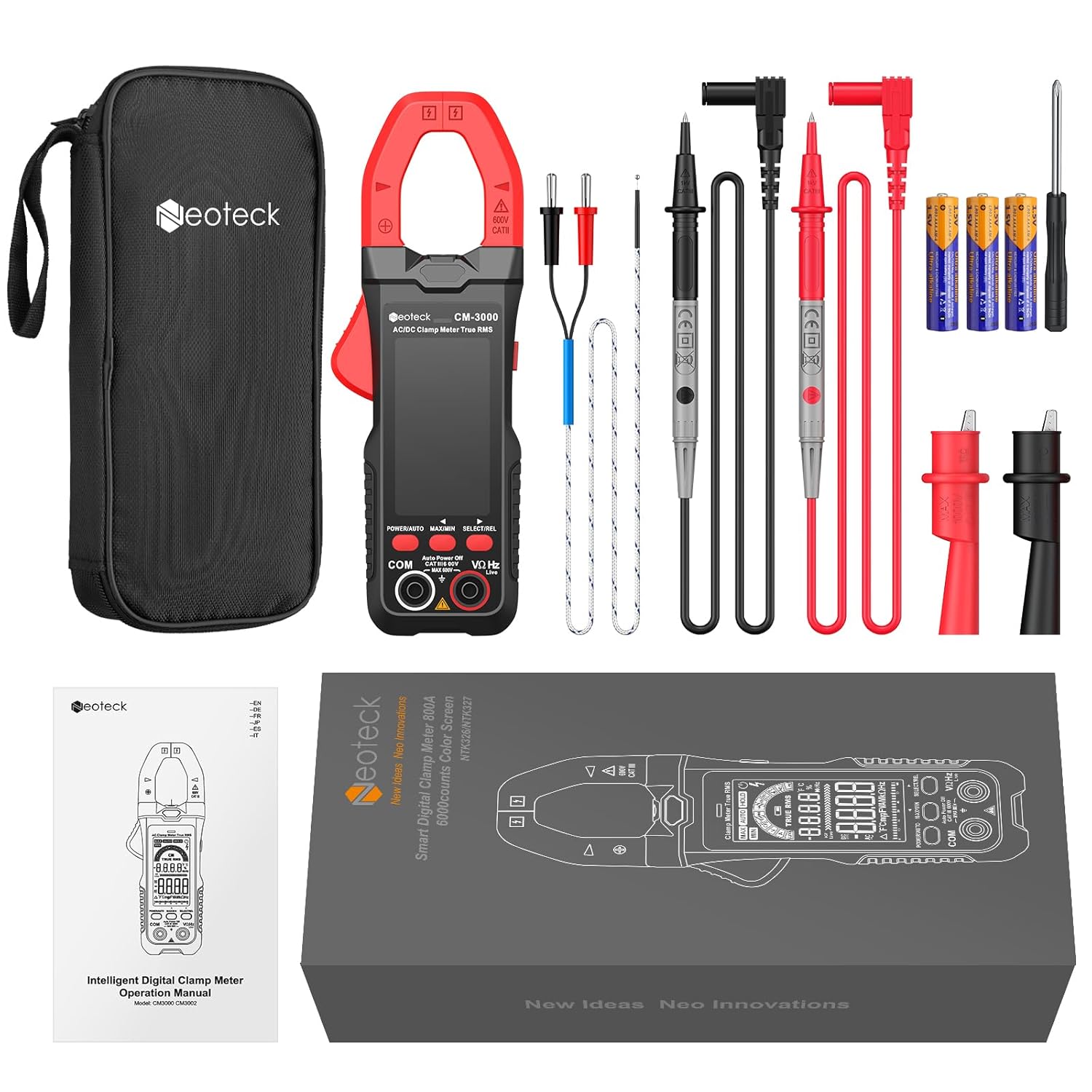
- 1 x Neoteck CM-3000 Clamp Meter
- 1 x Pair of 10A Test Leads with Alligator Clips
- 1 x Temperature Probe
- 1 x Screwdriver
- 3 x AAA Batteries
- 1 x User Manual
- 1 x Storage Pouch
Warranty and Support
Neoteck products are designed for reliability and performance. For warranty information, technical support, or assistance with your CM-3000 Clamp Multimeter, please refer to the contact information provided in the included user manual or visit the official Neoteck website. Keep your purchase receipt for warranty claims.


