1. Introduction
The HiLetgo USB Logic Analyzer is a compact, 8-channel digital signal analysis tool designed for debugging embedded systems and hardware development. It offers a sampling rate of up to 24 MHz, making it suitable for analyzing various digital protocols such as UART, IIC, and SPI. This manual provides essential information for setting up, operating, and maintaining your logic analyzer.
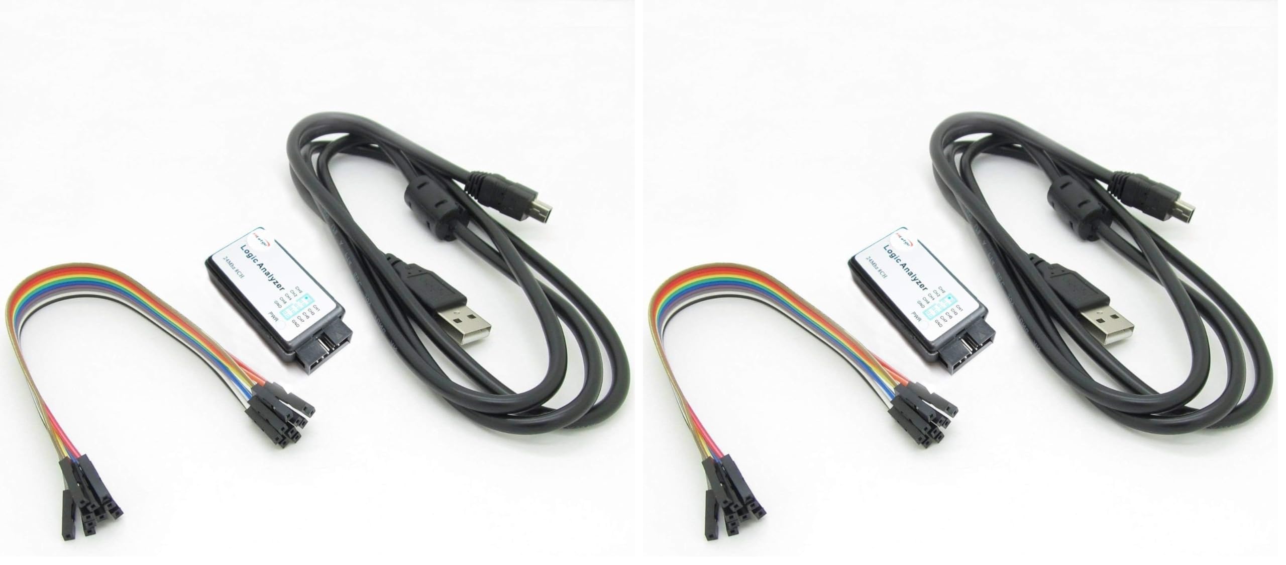
Figure 1.1: HiLetgo USB Logic Analyzer Device (angled view). This image shows the compact design of the logic analyzer with its USB port and pin headers visible.
2. Package Contents
Before proceeding, please verify that all items are present in your package:
- 1 x HiLetgo USB Logic Analyzer Device
- 1 x USB Cable (with EMI Ferrite Ring)
- 1 x Dupont Cable (8-channel, female-to-female)

Figure 2.1: Contents of the HiLetgo USB Logic Analyzer kit. This image displays the logic analyzer device, the USB cable with a ferrite bead, and the included Dupont jumper wires.
3. Setup
3.1 Hardware Connection
- Connect the mini-USB end of the provided USB cable to the USB port on the logic analyzer device.
- Connect the standard USB-A end of the cable to an available USB port on your computer. The device is powered via USB.
- Identify the 8 input channels (CH0-CH7) and Ground (GND) pins on the logic analyzer.
- Use the supplied Dupont cables to connect the logic analyzer's input channels to the test points on your target circuit. Ensure that the GND pin of the logic analyzer is connected to the ground of your target circuit.

Figure 3.1: Top view of the logic analyzer. This image clearly labels the 8 input channels (CH0-CH7) and the Ground (GND) pins, along with the Power (PWR) indicator.
3.2 Software Installation
This device is compatible with open-source software such as Sigrok PulseView. Follow these general steps for software setup:
- Download Software: Download the latest version of Sigrok PulseView from the official Sigrok website.
- Install Drivers: The logic analyzer typically requires a specific USB driver (e.g., WinUSB) to be installed. The Zadig utility is commonly used on Windows to install the correct driver for the device, which is often recognized as a "Saleae Logic" analyzer.
- Verify Connection: After installing the driver, launch PulseView. The software should automatically detect the device. If not, you may need to restart PulseView or try different USB ports on your computer.
4. Operating Instructions
4.1 Basic Operation with PulseView
- Select Device: In PulseView, ensure the "Saleae Logic" device is selected.
- Configure Channels: Enable the channels (CH0-CH7) you wish to monitor.
- Set Sampling Rate: Choose an appropriate sampling rate. The device supports rates up to 24 MHz. For most applications around 10 MHz, a 24 MHz sampling rate is sufficient. Available rates include 24MHz, 16MHz, 12MHz, 8MHz, 4MHz, 2MHz, 1MHz, 500KHz, 250KHz, 200KHz, 100KHz, 50KHz, and 25KHz.
- Start Capture: Click the "Run" or "Capture" button to begin data acquisition.
- Analyze Data: Once data is captured, you can use PulseView's features to zoom, pan, and apply protocol decoders (e.g., UART, I2C, SPI) to interpret the signals.

Figure 4.1: Example of the PulseView software interface. This image shows digital waveforms captured and displayed, with options for analysis and decoding.
4.2 Voltage Compatibility
The logic analyzer is designed to work with various voltage systems:
- Input Voltage Range: -0.5V to 5.25V
- Input Low Voltage: -0.5V to 0.8V
- Input High Voltage: 2.0V to 5.25V
It is compatible with 5V, 3.3V, 2.5V, and 2.0V systems. While it may function with 1.8V systems, it is not officially recommended.
5. Maintenance
To ensure the longevity and proper functioning of your HiLetgo USB Logic Analyzer, follow these maintenance guidelines:
- Storage: Store the device in a dry, dust-free environment away from direct sunlight and extreme temperatures.
- Cleaning: Use a soft, dry cloth to clean the exterior of the device. Avoid using liquid cleaners or solvents.
- Handling: Handle the device and its cables with care. Avoid excessive force when connecting or disconnecting cables.
- Input Protection: Do not expose the input channels to voltages outside the specified range (-0.5V to 5.25V) to prevent damage to the internal microcontroller.
6. Troubleshooting
- Device Not Detected:
- Ensure the USB cable is securely connected to both the logic analyzer and your computer.
- Verify that the correct USB driver (e.g., WinUSB via Zadig) is installed for the device.
- Try connecting the device to a different USB port on your computer. Some systems may have specific port compatibility issues.
- Restart the PulseView software or your computer after driver installation.
- No Signal Capture:
- Check that the Dupont cables are correctly connected from the logic analyzer to the target circuit's test points, including the ground connection.
- Ensure the target circuit is powered on and functioning correctly.
- Verify that the correct channels are enabled in the PulseView software.
- Adjust the sampling rate. If the signal is too fast or too slow for the current rate, it might not be captured accurately.
- Garbled or Incorrect Waveforms:
- Confirm that the ground connection between the logic analyzer and the target circuit is solid.
- Check for noise in the signal path. Ensure connections are short and shielded if necessary.
- Verify that the input voltage levels from your target circuit are within the specified operating range of the logic analyzer.
7. Specifications
| Feature | Specification |
|---|---|
| Channels | 8 |
| Max Sampling Rate | 24 MHz (24M samples/second per channel) |
| Supported Sampling Rates | 24MHz, 16MHz, 12MHz, 8MHz, 4MHz, 2MHz, 1MHz, 500KHz, 250KHz, 200KHz, 100KHz, 50KHz, 25KHz |
| Input Voltage Range | -0.5V to 5.25V |
| Input Low Voltage | -0.5V to 0.8V |
| Input High Voltage | 2.0V to 5.25V |
| Compatible Systems | 5V, 3.3V, 2.5V, 2.0V (1.8V not recommended) |
| Input Impedance | 1MΩ || 10pF (typical, approximate) |
| Crystal Oscillator | +/-20ppm, 24MHz |
| Pulse-width Measurement Error | +/- 42ns (at 24MHz) |
| Connectivity | USB 2.0 |
| Dimensions (Approx.) | 7.6 x 3.5 x 0.55 inches (Package Dimensions) |
| Weight (Approx.) | 4.8 ounces (0.14 Kilograms) |
8. Warranty and Support
8.1 Warranty Information
This product is covered by a standard manufacturer's warranty. Please refer to the retailer's return policy for specific details regarding returns and replacements. Typically, a 30-day return/replacement policy is offered.
8.2 Technical Support
For technical assistance or any issues you encounter with your HiLetgo USB Logic Analyzer, please contact HiLetgo support directly:
- Email: support@hiletgo.com
- Website: Visit the official HiLetgo store on Amazon for product information and updates: HiLetgo Amazon Store


