1. Introduction
The UNI-T UT693A-T30 is a versatile 4-in-1 fiber optic cable tester designed for optical communication testing. It integrates an optical power meter, a 30mW visual fault locator (VFL), an RJ45 network cable tester, and an LED flashlight. This device offers high precision, multifunctionality, and portability, making it suitable for various fiber optic communication scenarios including telecommunications, data centers, broadcasting networks, and industrial fiber optic sensing.
What's in the Box
- UT693A-T30 4-in-1 Fiber Optic Cable Tester
- USB Type-C Charging Cable
- User Manual
2. Safety Information
- Laser Safety: The Visual Fault Locator (VFL) emits a red laser. Avoid direct eye exposure to the laser beam. Do not look directly into the fiber end or the VFL output port when the VFL is active.
- Battery Safety: Use only the provided charging cable and a compatible power adapter. Do not disassemble or short-circuit the built-in lithium battery. Avoid exposing the device to extreme temperatures.
- Environmental Conditions: Operate the device within specified temperature and humidity ranges. Avoid using in dusty or wet environments.
- Cleaning: Disconnect the device from power before cleaning. Use a soft, dry cloth. Do not use abrasive cleaners or solvents.
3. Product Overview
The UT693A-T30 combines essential fiber optic testing functions into a compact, handheld device. Its robust design ensures durability and ease of use in various field conditions.
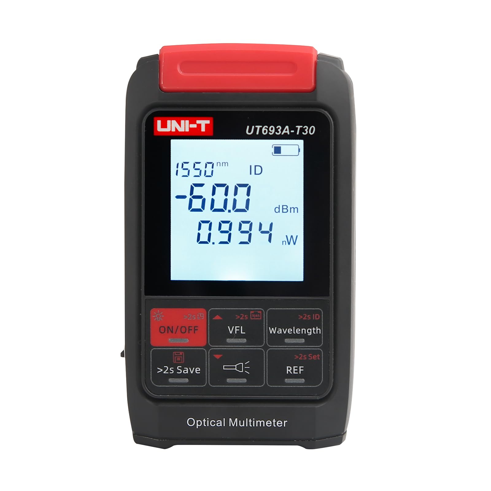
Figure 3.1: The UNI-T UT693A-T30 in use, demonstrating its compact size and display interface.
Key Features:
- Optical Power Meter (OPM): Measures optical power with a range of -70 to +10 dBm across 10 wavelengths (850nm, 980nm, 1270nm, 1300nm, 1310nm, 1490nm, 1550nm, 1577nm, 1625nm, 1650nm).
- Visual Fault Locator (VFL): 30mW red light source for identifying fiber breaks, bends, and connector contamination over approximately 30km.
- RJ45 Network Test: Verifies the sequence of a single Ethernet cable to confirm signal transmission.
- LED Lighting: Built-in flashlight for working in dark environments.
- Data Storage: Stores up to 500 sets of measurement data.
- Universal Interface: 2.5mm universal interface compatible with SC, FC, and ST connectors.
- Rechargeable Battery: Built-in 450mAh lithium battery, charged via Type-C interface.
4. Setup
4.1 Charging the Device
- Connect the provided Type-C USB cable to the charging port on the side of the UT693A-T30.
- Connect the other end of the USB cable to a standard USB power adapter (not included) or a computer's USB port.
- The battery indicator on the display will show the charging status. A full charge typically takes a few hours.
4.2 Connecting Fiber Optic Cables
The device features a 2.5mm universal interface for fiber optic connections.
- Remove the protective dust cap from the fiber optic input port.
- Ensure the fiber optic connector (SC, FC, or ST) is clean. Use a fiber optic cleaner if necessary.
- Carefully insert the fiber optic connector into the input port until it clicks into place.
4.3 Connecting RJ45 Cable
- Locate the RJ45 port on the device.
- Insert the RJ45 connector of the network cable firmly into the port.
5. Operating Instructions
5.1 Power On/Off
- Power On: Press and hold the ON/OFF button for approximately 2 seconds.
- Power Off: Press and hold the ON/OFF button for approximately 2 seconds.
5.2 Optical Power Meter (OPM) Function
The device defaults to OPM mode upon power-on.

Figure 5.1: Optical Power Meter displaying a measurement in dBm and nW.
- Wavelength Selection: Press the Wavelength button to cycle through the 10 available wavelengths (850nm, 980nm, 1270nm, 1300nm, 1310nm, 1490nm, 1550nm, 1577nm, 1625nm, 1650nm). Select the wavelength corresponding to the signal being tested.
- Measurement: Once the correct wavelength is selected and the fiber is connected, the device will display the optical power in dBm and nW/uW.
- Setting Reference (REF): To measure relative power loss, press the REF button. The current power reading will be set as the reference (0 dB), and subsequent measurements will show the difference. Press REF again to exit reference mode.
- Data Storage: Press and hold the >2s Save button to save the current measurement data. The device can store up to 500 sets of data.
- Viewing Stored Data: Briefly press the >2s Save button to enter data viewing mode. Use the arrow buttons (if available, or cycle through save button) to navigate through stored records.
5.3 Visual Fault Locator (VFL) Function
The VFL function helps identify physical faults in fiber optic cables.
- Activate VFL: Press the VFL button. The red laser will emit from the VFL port.
- Connect Fiber: Insert the fiber optic cable to be tested into the VFL port.
- Identify Faults: Observe the fiber along its length. Red light escaping from the fiber indicates a break, bend, or poor connection.
- Deactivate VFL: Press the VFL button again to turn off the laser.
5.4 RJ45 Network Testing
This function checks the continuity and wiring sequence of an RJ45 Ethernet cable.
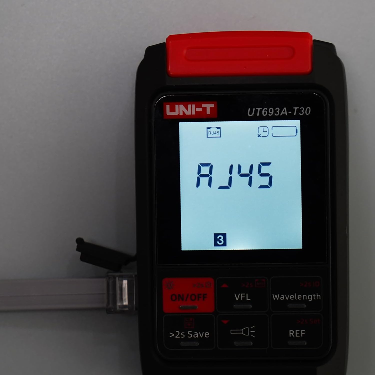
Figure 5.2: RJ45 network testing in progress, showing the cable number.
- Enter RJ45 Test Mode: Press the dedicated RJ45 test button (if available, or cycle through modes using a multi-function button). The display will show 'RJ45'.
- Connect Cable: Connect one end of the RJ45 cable to the device's RJ45 port.
- Observe Results: The device will sequentially display the status of each wire pair. A correct sequence indicates a healthy cable. Any missing or incorrect sequence indicates a fault.
5.5 LED Lighting
To activate the built-in LED flashlight:
- Press the LED Light button (represented by a flashlight icon) to turn the light on or off.
6. Maintenance
6.1 Cleaning
- Device Exterior: Wipe the device's exterior with a soft, dry, lint-free cloth. Do not use liquid cleaners.
- Fiber Optic Connectors: Always ensure fiber optic connectors are clean before insertion. Use specialized fiber optic cleaning tools (e.g., fiber cleaning pens or wipes with isopropyl alcohol) to remove dust and contaminants. Contaminated connectors can lead to inaccurate measurements and damage to the device.
6.2 Battery Care
- Charge the device regularly, especially if it has not been used for an extended period, to maintain battery health.
- Avoid fully discharging the battery frequently.
- Store the device in a cool, dry place when not in use.
6.3 Storage
- When not in use, store the device in its protective casing to prevent damage.
- Keep dust caps on all ports to prevent dust and debris from entering.
7. Troubleshooting
| Problem | Possible Cause | Solution |
|---|---|---|
| Device does not power on. | Low battery or depleted battery. | Charge the device using the Type-C USB cable. |
| Inaccurate OPM readings. | Dirty fiber optic connectors; incorrect wavelength selected; damaged fiber. | Clean connectors thoroughly; ensure correct wavelength is selected; inspect fiber for damage. |
| VFL red light is weak or absent. | VFL port is dirty; VFL module fault. | Clean the VFL output port; if problem persists, contact support. |
| RJ45 test shows incorrect wiring. | Faulty RJ45 cable; improper connection. | Test with a known good cable; ensure cable is fully inserted. |
| Device freezes or is unresponsive. | Software glitch. | Press and hold the ON/OFF button for an extended period (e.g., 10-15 seconds) to force a restart. |
8. Specifications
| Parameter | Specification |
|---|---|
| Model | UT693A-T30 |
| Optical Power Measurement Range | -70 to +10 dBm |
| Wavelengths | 850nm, 980nm, 1270nm, 1300nm, 1310nm, 1490nm, 1550nm, 1577nm, 1625nm, 1650nm |
| VFL Output Power | 30mW |
| VFL Testing Range | Approximately 30km |
| Fiber Optic Interface | 2.5mm Universal (SC, FC, ST compatible) |
| RJ45 Test Function | Yes |
| Data Storage | 500 sets |
| Battery Type | Built-in 450mAh Rechargeable Lithium Battery |
| Charging Interface | Type-C USB |
| LED Lighting | Yes |
| Item Weight | Approximately 1.32 pounds (0.6 kg) |
| Manufacturer | UNI-T |
9. Warranty and Support
9.1 Warranty Information
This product is covered by a limited manufacturer's warranty. Please refer to the warranty card included with your purchase or contact the retailer for specific warranty terms and conditions. The warranty typically covers defects in materials and workmanship under normal use.
9.2 Technical Support
For technical assistance, troubleshooting, or service inquiries, please contact your authorized UNI-T distributor or the retailer from whom you purchased the product. Provide your product model number (UT693A-T30) and a detailed description of the issue when seeking support.


